
Mastering the Arduino Gyro Sensor: From Raw MEMS to Sensor Fusion
Integrating an Arduino gyro sensor into your robotics, drones, or motion-tracking projects requires more than just plugging in four wires. Micro-Electromechanical Systems (MEMS) gyroscopes measure angular velocity (degrees per second), meaning you must mathematically integrate the data over time to find absolute orientation. This guide covers the exact wiring, I2C bus physics, and C++ code implementation for the two most dominant sensors in the 2026 DIY ecosystem: the budget-friendly MPU-6050 and the premium, sensor-fusion-equipped BNO055.
Hardware Selection Matrix: Which Gyro Module Do You Need?
Before writing code, select the right IMU (Inertial Measurement Unit). While the MPU-6050 remains the undisputed king of budget prototyping, its lack of onboard sensor fusion makes it prone to yaw drift. Here is how the top contenders compare for modern microcontroller projects.
| Sensor Model | DOF (Axes) | Onboard Fusion | 2026 Avg Price | Default I2C Address |
|---|---|---|---|---|
| MPU-6050 (GY-521) | 6-Axis | No (Requires MCU Math) | $2.50 - $4.00 | 0x68 |
| BNO055 | 9-Axis | Yes (ARM Cortex-M0) | $18.00 - $24.00 | 0x28 |
| LSM6DS3 | 6-Axis | No (Has FIFO buffer) | $6.00 - $9.00 | 0x6A |
| MPU-9250 | 9-Axis | No | $5.00 - $8.00 | 0x68 |
Wiring the MPU-6050: Avoiding the I2C Voltage Trap
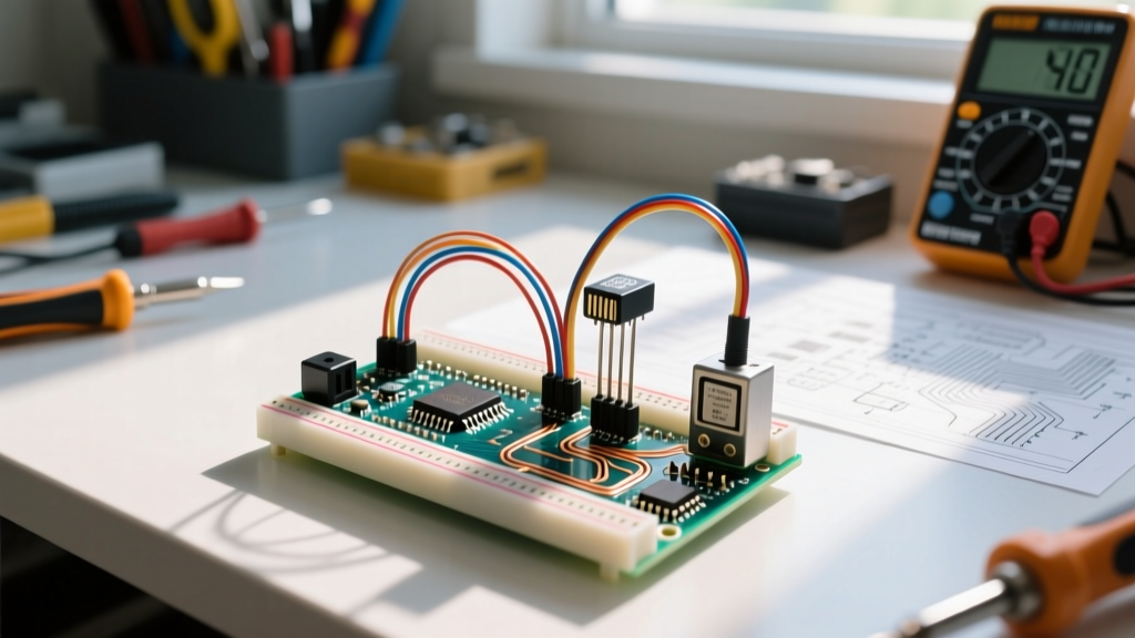
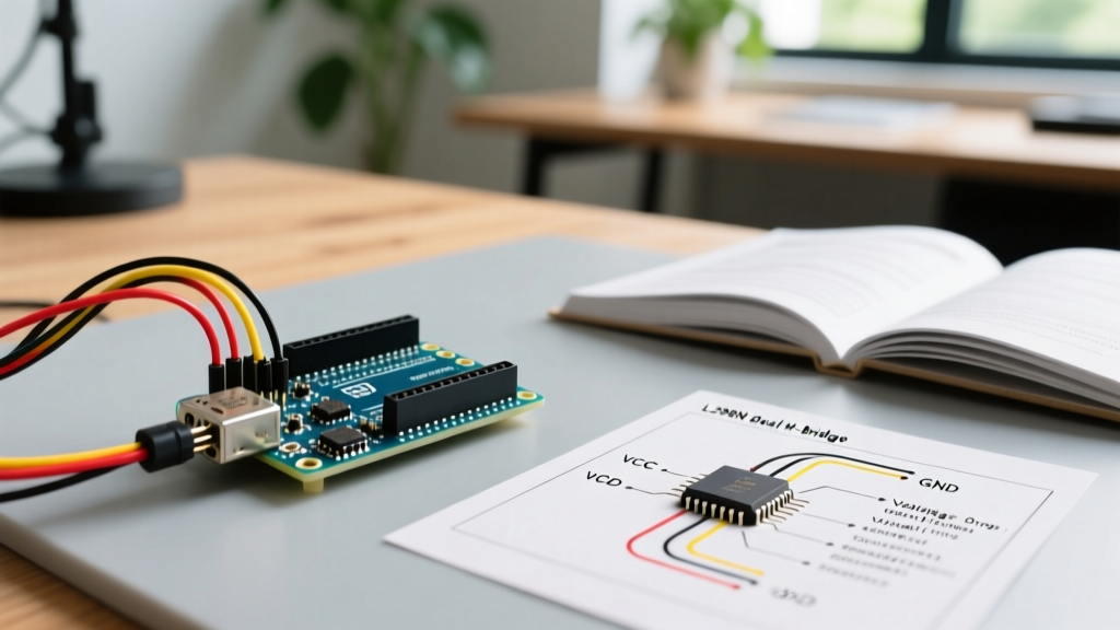
The most common failure mode when wiring an Arduino gyro sensor like the MPU-6050 to a 5V Arduino Uno or Nano is ignoring logic level thresholds. The raw MPU-6050 silicon operates at 3.3V. However, the ubiquitous GY-521 breakout board includes an onboard LDO (Low Dropout Regulator) and logic level shifters, allowing you to safely power it from the 5V pin.
Standard GY-521 to Arduino Uno Pinout
- VCC to 5V (Onboard LDO steps this down to 3.3V for the chip)
- GND to GND
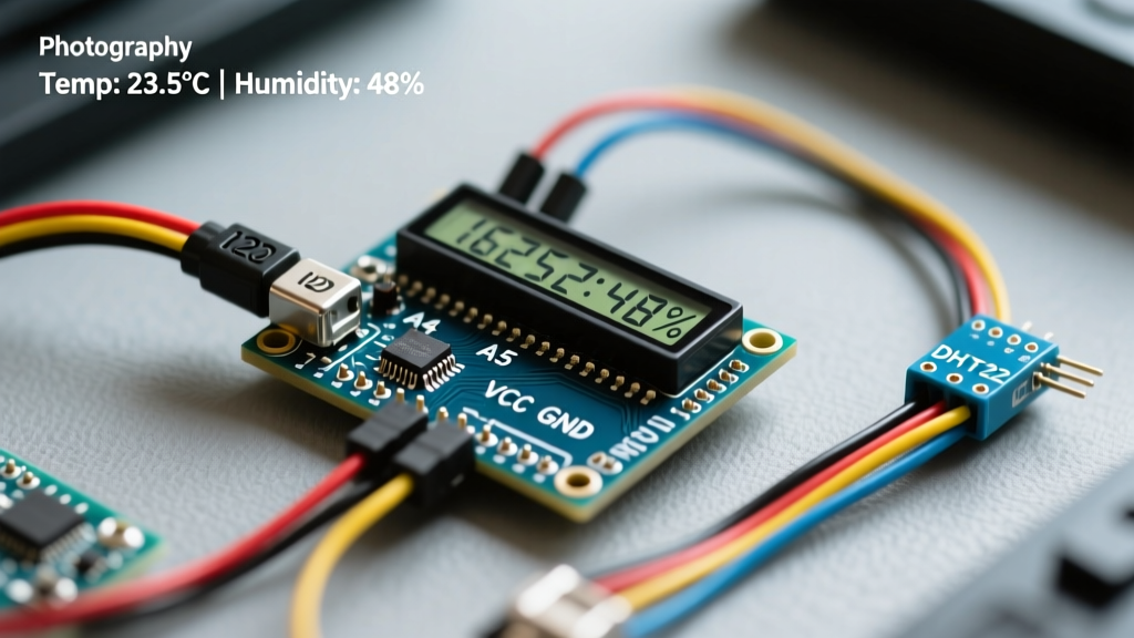
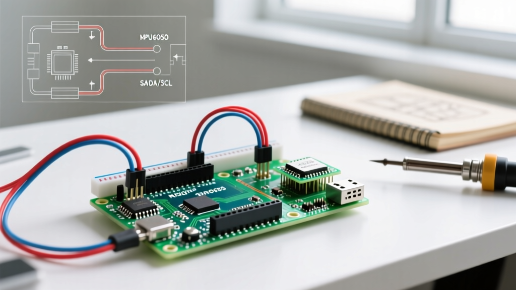
- SCL to A5 (Hardware I2C Clock)
- SDA to A4 (Hardware I2C Data)
The Pull-Up Resistor Edge Case
The I2C bus is open-drain, meaning it requires pull-up resistors to return the signal to HIGH. The GY-521 breakout includes 4.7kΩ pull-up resistors tied to 3.3V. If you are daisy-chaining multiple sensors or running the bus at 400kHz (Fast Mode), the parasitic capacitance of long wires will degrade your signal edges. According to the NXP I2C Bus Specification, you may need to drop to 2.2kΩ resistors or reduce wire length to under 30cm to prevent bus lockups and corrupted gyro registers.
Extracting Yaw, Pitch, and Roll: C++ Code Implementation
Raw gyroscope data outputs in Degrees Per Second (DPS). To get an angle, you must multiply the DPS by the time delta (dt). However, this integration accumulates microscopic noise, resulting in severe 'gyro drift' over just a few minutes. To solve this, we fuse the gyro data with the onboard accelerometer using a Mahony or Madgwick filter.
Below is a streamlined implementation using the widely supported Adafruit_MPU6050 and Adafruit_AHRS libraries, which handle the complex quaternion math required for stable orientation tracking.
#include <Wire.h>
#include <Adafruit_MPU6050.h>
#include <Adafruit_Sensor.h>
#include <Adafruit_AHRS_NXP.h>

Adafruit_MPU6050 mpu;
Adafruit_NXPMadgwick filter;

void setup() {
  Serial.begin(115200);
  Wire.begin();

  // Initialize with specific range settings for robotics
  // +/- 500 degrees/sec prevents clipping during fast robot turns
  mpu.setGyroRange(MPU6050_RANGE_500_DEG);
  mpu.setAccelerometerRange(MPU6050_RANGE_4_G);
  mpu.setFilterBandwidth(MPU6050_BAND_21_HZ);
}

void loop() {
  sensors_event_t a, g, temp;
  mpu.getEvent(&a, &g, &temp);

  // Feed raw data into the Madgwick filter (100Hz sample rate)
  filter.update(g.gyro.x, g.gyro.y, g.gyro.z,
                a.acceleration.x, a.acceleration.y, a.acceleration.z,
                0, 0, 0, 0.01);

  float roll = filter.getRoll();
  float pitch = filter.getPitch();
  float yaw = filter.getYaw();

  Serial.print("Roll: "); Serial.print(roll);
  Serial.print(", Pitch: "); Serial.print(pitch);
  Serial.print(", Yaw: "); Serial.println(yaw);
  delay(10);
}
Upgrading to Absolute Orientation: The Bosch BNO055
If your project requires absolute heading (like a compass) or you cannot afford the CPU cycles to run a Kalman filter on your microcontroller, the Bosch BNO055 is the definitive upgrade. As detailed in the Adafruit BNO055 Sensor Guide, this chip contains an ARM Cortex-M0 core that performs sensor fusion internally, combining a 3-axis gyro, 3-axis accelerometer, and 3-axis magnetometer at 100Hz.
BNO055 Wiring Differences
Unlike the MPU-6050, the BNO055 breakout boards usually lack 5V tolerance on the I2C lines. If you are using a 5V Arduino, you must use a bi-directional logic level converter (like the BSS138 MOSFET-based shifters) between the SDA/SCL lines. The wiring also introduces two new pins:
- RST: Active low reset. Tie to a digital pin to hard-reset the sensor if the I2C bus hangs.
- INT: Interrupt pin. Configure this to trigger when the sensor detects a 'tap' or when new orientation data is ready, saving your MCU from constant polling.
Advanced Troubleshooting & Calibration Realities
Even with perfect wiring, environmental factors will corrupt your Arduino gyro sensor data. Here is how to handle the most common edge cases encountered in professional and hobbyist deployments.
1. High-Frequency Vibration Noise
MEMS gyroscopes are highly sensitive to acoustic and mechanical vibrations. If your sensor is mounted directly to a drone frame or a chassis with DC motors, the motor PWM frequencies will alias into the gyro readings, causing violent oscillation in your PID control loops. Solution: Mount the IMU on a 1mm silicone dampening pad or use the sensor's internal Digital Low Pass Filter (DLPF). The TDK InvenSense MPU-6050 Datasheet recommends setting the DLPF to 42Hz or 21Hz for high-vibration robotics applications.
2. Magnetometer Hard/Soft Iron Distortion
If using a 9-DOF sensor for Yaw (compass heading), nearby copper traces, steel screws, and battery cables will warp the local magnetic field. You must perform a hard-iron (offset) and soft-iron (scaling) calibration. Most modern libraries include a 'figure-8' calibration routine that writes these offsets to the sensor's EEPROM or the MCU's flash memory on boot. Skipping this step will result in a yaw drift of up to 45 degrees when the robot rotates near its own motors.
3. I2C Bus Lockups
If your Arduino freezes randomly, the I2C bus has likely locked in a LOW state due to an ESD spike or a loose ground connection. Implement a watchdog timer in your code and ensure your ground wires are as short and thick as your power wires to minimize ground bounce.
Final Verdict
For balancing robots and basic motion tracking where budget is the primary constraint, the MPU-6050 paired with a Madgwick filter remains an incredibly capable Arduino gyro sensor setup. However, for autonomous navigation, outdoor rovers, and projects requiring zero-drift absolute heading, investing the extra $15 in a BNO055 will save you weeks of frustrating DSP (Digital Signal Processing) debugging.