
The Evolution of HD44780 Display Drivers
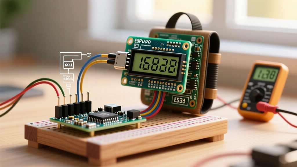
When makers and engineers research how to connect LCD Arduino displays, they are almost universally referring to the 16x2 or 20x4 character modules built around the Hitachi HD44780 controller. In 2026, the traditional method of wiring 12 separate jumper cables for 4-bit parallel communication is considered legacy practice. The integration of I2C (Inter-Integrated Circuit) backpacks has reduced the hardware footprint to just four wires (VCC, GND, SDA, SCL), preserving critical GPIO pins for advanced sensor arrays and motor drivers.
However, the hardware is only half the battle. The real challenge lies in the software ecosystem. Navigating library conflicts, hardcoded I2C addresses, and pin-mapping anomalies causes more project failures than incorrect wiring. This guide bypasses the outdated tutorials and provides a definitive, modern driver implementation strategy for I2C LCD integration.
Hardware Matrix: Parallel vs. I2C Backpacks
Before writing a single line of code, it is crucial to understand the electrical and economic trade-offs of your display configuration. Standard 1602 modules cost around $2.50, while I2C-equipped versions retail for approximately $3.50 to $4.50—a negligible premium for the massive reduction in wiring complexity.
| Feature | Standard Parallel (16-Pin) | I2C Backpack (PCF8574) |
|---|---|---|
| MCU Pins Required | 6 to 11 (depending on RW tie) | 2 (SDA, SCL) |
| Typical I2C Address | N/A | 0x27 or 0x3F |
| Wiring Complexity | High (prone to loose dupont cables) | Low (standardized 4-pin JST or header) |
| Bus Capacitance Limit | N/A (Direct GPIO) | 400pF (limits cable length to ~1 meter) |
| Backlight Control | Requires dedicated PWM pin | Software controlled via I2C register |
The Library Landscape: Choosing the Right Driver
The Arduino ecosystem is littered with abandoned or poorly maintained LCD libraries. Selecting the wrong one is the primary reason developers struggle with how to connect LCD Arduino setups successfully. Here is the 2026 consensus on driver selection:
- LiquidCrystal (Built-in): Excellent for raw parallel wiring, but completely useless for I2C backpacks without a messy wrapper. Avoid for I2C projects.
- LiquidCrystal_I2C (Frank de Brabander): The legacy standard. While it still works, it requires manual pin-mapping configuration and hardcodes I2C addresses, leading to massive headaches when you swap a display from a different manufacturer.
- hd44780 (Bill Perry): The undisputed modern gold standard. This library auto-detects the I2C address, automatically maps the PCF8574 pinouts, and includes built-in diagnostics. It is the only library recommended for new designs.
Step 1: I2C Address Discovery (The PCF8574 Factor)
The I2C backpacks soldered to the back of HD44780 displays utilize an I/O expander chip—almost always a variant of the PCF8574. According to the NXP PCF8574 I/O Expander Datasheet, the physical address pins (A0, A1, A2) dictate the bus address. However, manufacturers use two different silicon revisions:
- PCF8574T (Texas Instruments / NXP): Default address is
0x27. - PCF8574AT (NXP): Default address is
0x3F.
If you attempt to initialize the display using the wrong address, the screen will remain blank, and the I2C bus may lock up. Always run an I2C scanner sketch (available via the Arduino IDE File > Examples > Wire > I2CScanner menu) before writing your main application logic. The Arduino Wire Library Documentation provides the foundational protocol for this bus scanning process.
Step 2: Wiring for Signal Integrity
I2C is highly susceptible to noise and capacitance. When connecting your LCD to an Arduino Uno R4 Minima or an ESP32, adhere to these electrical rules:
- Pull-Up Resistors: Most I2C backpacks include 4.7kΩ pull-up resistors on the SDA and SCL lines. If you are daisy-chaining multiple sensors on the same bus, the parallel resistance may drop too low (below 1kΩ), causing signal degradation. Measure the bus with a multimeter if you experience ghosting.
- Decoupling Capacitors: Solder a 100nF (0.1µF) ceramic capacitor directly across the VCC and GND pins on the LCD backpack. The backlight LED draws up to 80mA, which can cause voltage sags and reset the HD44780 controller mid-frame.
- Pin Mapping on Modern Boards: On the classic Uno R3, SDA/SCL are duplicated on A4/A5. On newer architectures like the Uno R4 WiFi or Nano ESP32, you must use the dedicated SDA/SCL header pins, as the analog pins do not route to the hardware I2C peripheral.
Step 3: Implementation with the hd44780 Library
Install the hd44780 library via the Arduino Library Manager. You must specifically select the hd44780_I2Cexp I/O class, which handles PCF8574 backpacks. Below is the optimized initialization code that leverages auto-detection.
#include <Wire.h>
#include <hd44780.h>
#include <hd44780ioClass/hd44780_I2Cexp.h>

// Auto-detect I2C address and pin mapping
hd44780_I2Cexp lcd;

const int LCD_COLS = 16;
const int LCD_ROWS = 2;

void setup() {
  // Initialize LCD with auto-detected parameters
  int status = lcd.begin(LCD_COLS, LCD_ROWS);

  // Check for initialization failure
  if (status != 0) {
    // Use built-in diagnostic LED to blink error code
    hd44780::fatalError(status);
  }

  lcd.print('System Online');
  lcd.setCursor(0, 1);
  lcd.print('Flux OS v2.6');
}

void loop() {
  // Update sensor data without blocking the I2C bus
}
Pro Tip: The hd44780::fatalError(status) function is invaluable. If the library cannot find the display on the I2C bus, it will blink the Arduino's onboard LED (Pin 13) in a specific pattern to indicate whether the failure was due to a missing device, a bus collision, or an unsupported chip. Refer to Bill Perry's hd44780 Library Repository for the exact blink-code matrix.
Advanced Troubleshooting & Failure Modes
Even with perfect code, hardware anomalies occur. Here is how to diagnose the three most common edge cases when integrating I2C character displays.
1. Solid White Blocks on the First Row
Symptom: The backlight is on, but row 1 shows solid white (or dark blue) rectangles, and row 2 is blank.
Diagnosis: The HD44780 controller has powered up, but the initialization sequence failed. This is almost always caused by a voltage drop on the VCC line during the backlight surge, or a missing 100nF decoupling capacitor.
Fix: Add the decoupling capacitor. If using a 3.3V MCU (like an ESP32), ensure you are using a 3.3V-compatible LCD module or a logic level shifter; the HD44780 requires 4.5V to 5.5V for reliable 5V logic thresholds.
2. Ghosting, Flickering, or Random Characters
Symptom: The display works initially but corrupts into Japanese characters or random symbols after a few minutes, especially when motors or relays switch.
Diagnosis: I2C bus capacitance has exceeded the 400pF limit, or EMI from inductive loads is corrupting the SDA/SCL clock edges.
Fix: Keep I2C wires under 30cm. Route SDA/SCL away from motor power lines. If long runs are mandatory, switch to an I2C bus extender IC like the P82B715, which converts the signal to a differential pair for long-distance travel.
3. Contrast Potentiometer Ineffective
Symptom: Turning the blue trim-pot on the back of the I2C backpack does nothing; the text remains invisible.
Diagnosis: The V0 (contrast) pin on the backpack is not receiving the correct voltage reference, often due to a cold solder joint from the factory on the 16-pin header connecting the backpack to the glass substrate.
Fix: Reflow the 16-pin header joints with a soldering iron set to 350°C for 2 seconds per pin, using a mild flux core to ensure wicking into the plated through-holes.
Frequently Asked Questions
Can I change the I2C address of my LCD backpack?
Yes. By bridging the A0, A1, and A2 jumper pads on the PCF8574 backpack with solder, you can alter the address. However, with the hd44780 library's auto-detection feature, manual address reassignment is rarely necessary unless you have multiple identical displays on the same bus.
Why does my LCD freeze when I use the Servo library?
The standard Arduino Servo library disables interrupts while writing to the timer registers. Because I2C communication relies heavily on interrupts via the Wire library, a servo update can corrupt an ongoing I2C transmission to the LCD. Use the ServoTimer2 library or hardware PWM pins to prevent bus collisions.