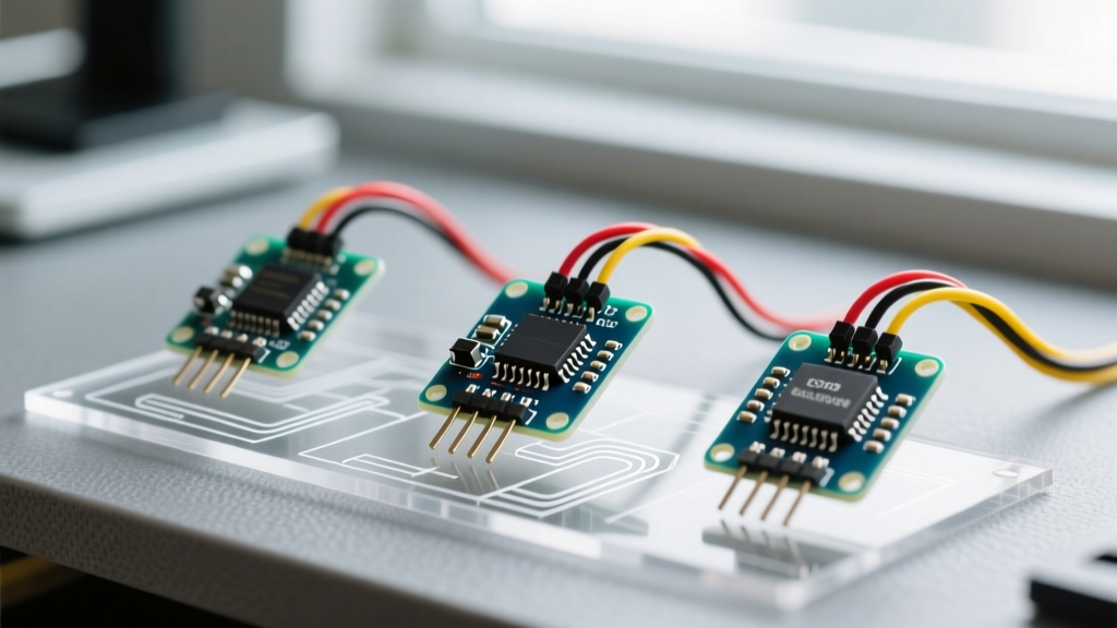

Choosing the Right Arduino Hall Effect Sensor for Your Project
When integrating magnetic field detection into your microcontroller projects, selecting the correct arduino hall effect sensor is critical for reliable operation. While all Hall effect sensors rely on the same underlying physics—generating a voltage differential across a conductor when exposed to a magnetic field—their output architectures vary wildly. Picking a digital switch when you need a linear ratiometric output will result in binary data where you need analog granularity, while using a linear sensor for simple RPM counting wastes ADC resources and complicates your firmware.
In this comprehensive component comparison, we break down the three primary Hall effect sensor architectures available to DIYers and engineers in 2026: Digital Unipolar Switches, Linear Ratiometric Sensors, and Digital Latches. We will examine specific industry-standard ICs, their real-world pricing, wiring pitfalls, and firmware integration strategies.
Component Comparison Matrix
Before diving into the circuit-level details, review this specification matrix of the most common Hall effect ICs found on breakout modules today.
| IC Model | Architecture | Output Type | Operating Voltage | Magnetic Trigger (Typical) | Est. Module Price (2026) |
|---|---|---|---|---|---|
| A3144 (Allegro) | Unipolar Switch | Open-Drain Digital | 4.5V - 24V | 30 Gauss (South Pole) | $0.60 - $0.90 |
| SS49E (Honeywell) | Linear Ratiometric | Analog Voltage | 2.7V - 6.5V | Continuous (±14mV/G) | $1.10 - $1.50 |
| DRV5053 (TI) | Linear (Fixed) | Analog / PWM | 2.5V - 38V | Continuous (Configurable) | $1.20 - $1.80 |
| US1881 (Melexis) | Bipolar Latch | Open-Drain Digital | 3.5V - 24V | ±40 Gauss (N/S Latch) | $0.75 - $1.00 |
1. Digital Unipolar Switches: The A3144
The Allegro A3144 is the undisputed workhorse for simple proximity detection. It acts as a unipolar switch, meaning it only responds to one magnetic pole (typically the South pole). When the magnetic flux density exceeds the operate point (B_OP, usually around 30 Gauss), the internal N-channel MOSFET pulls the output pin LOW. When the field drops below the release point (B_RP, around 15 Gauss), the output goes HIGH.
Wiring and Pull-Up Pitfalls
Because the A3144 features an open-drain output, it cannot drive a pin HIGH on its own. You must use a pull-up resistor. Most cheap breakout boards include a 10kΩ surface-mount pull-up resistor tied to the module's VCC pin.
- 5V Logic (Arduino Uno/Mega): Wire VCC to 5V, GND to GND, and the DO (Digital Out) pin directly to your MCU. The internal 10kΩ pull-up is sufficient.
- 3.3V Logic (ESP32/Teensy): The A3144 requires a minimum of 4.5V to operate reliably. You must power the sensor's VCC with 5V, but the 10kΩ pull-up on the board will pull the output to 5V, potentially damaging a 3.3V MCU GPIO. Solution: Disable the onboard pull-up (cut the trace or desolder the resistor) and use an external 4.7kΩ pull-up resistor tied to your MCU's 3.3V rail.
2. Linear Ratiometric Sensors: SS49E vs. DRV5053
If your project requires measuring the distance to a magnet, detecting the thickness of a ferromagnetic material, or building a custom linear throttle, you need a linear sensor. These output an analog voltage proportional to the magnetic field strength.
The Honeywell SS49E: Classic but Flawed
The SS49E outputs a ratiometric voltage. At zero magnetic field (neutral), the output sits at exactly VCC / 2. If you power it with 5.00V, the neutral point is 2.50V. As a South pole approaches, the voltage increases toward VCC; as a North pole approaches, it decreases toward 0V.
Expert Warning: Because the SS49E is ratiometric, any noise or droop on your 5V USB power rail directly corrupts your sensor reading. A 100mV drop in VCC shifts your neutral baseline by 50mV, resulting in false position data. Always use an external low-dropout (LDO) regulator or the MCU's internal voltage reference for ADC calculations when using the SS49E.
The Texas Instruments DRV5053: The Modern Standard
For new designs in 2026, the Texas Instruments DRV5053 is vastly superior to the SS49E for microcontroller integration. Unlike the SS49E, the DRV5053 offers fixed-sensitivity variants. Its analog output is referenced to an internal bandgap, not VCC. This means power supply ripple will not destroy your measurement accuracy. Furthermore, the DRV5053 operates natively down to 2.5V, making it perfect for direct interfacing with 3.3V ARM Cortex-M MCUs and ESP32 modules without level-shifting headaches.
ADC Mapping and Firmware Strategy
When reading a linear sensor with an Arduino Uno (10-bit ADC, 0-1023), map the raw ADC values to Gauss using the sensor's sensitivity rating. For the SS49E (14mV/G), a 100 Gauss field shifts the output by 1.4V. Ensure your ADC reference voltage is highly stable, or switch to an oversampling technique (reading the pin 16 times and bit-shifting) to achieve 12-bit effective resolution.
3. Digital Bipolar Latches: The US1881
Latches are frequently confused with standard switches, but their behavior is fundamentally different. A unipolar switch (A3144) turns off when the magnet is removed. A bipolar latch (US1881) turns ON when exposed to a South pole, and stays ON even after the magnet is removed. It will only turn OFF when exposed to a North pole.
When to Use a Latch
Latches are mandatory for brushless DC (BLDC) motor commutation and precise multi-pole encoder wheels. If you are building a custom e-bike cadence sensor using a ring magnet with alternating N/S poles, a standard switch will chatter or miss pulses at high RPMs due to its hysteresis and release timing. A latch guarantees a clean 50% duty-cycle square wave, making hardware interrupt counting on your Arduino flawless.
Real-World Troubleshooting and EMI Mitigation
Hall effect sensors are notoriously susceptible to Electromagnetic Interference (EMI), especially when deployed near stepper motors, relays, or switching power supplies. If your arduino hall effect sensor is triggering phantom interrupts, implement these hardware-level fixes before blaming your code:
- Local Decoupling: Solder a 100nF (0.1µF) X7R ceramic capacitor directly across the VCC and GND pins of the Hall IC. Do not rely solely on the capacitor on the breakout board, as the trace inductance from the pin header to the IC can render it ineffective at high frequencies.
- Twisted Pair Routing: When running sensor cables longer than 15cm, use twisted pair wire for the signal and ground lines. This cancels out common-mode magnetic noise picked up from adjacent motor cables.
- Software Debouncing: Mechanical vibration can cause a magnet to hover exactly on the sensor's B_OP threshold, resulting in rapid oscillation. Implement a minimum 5ms hardware-timer debounce in your ISR (Interrupt Service Routine) to ignore transient bounces.
Summary: Which Sensor Should You Buy?
Your component choice must align with your physical and electrical requirements. Choose the A3144 for simple, low-cost limit switches and basic RPM counting where 5V logic is available. Upgrade to the DRV5053 for precision analog measurements, custom joysticks, and 3.3V logic environments where power supply noise is a concern. Finally, deploy the US1881 latch exclusively for multi-pole magnetic encoders and BLDC motor commutation. For further wiring diagrams and basic code examples, the SparkFun Hall Effect Hookup Guide remains an excellent foundational resource for beginners.