
Why the MPU-6050 Dominates Beginner Projects
When makers and engineers need to measure rotational velocity or orientation, the gyroscope Arduino sensor market is overwhelmingly dominated by a single chip: the MPU-6050. Originally developed by InvenSense and now manufactured by TDK, this 6-axis MotionTracking device combines a 3-axis MEMS gyroscope and a 3-axis accelerometer into a tiny 4x4x0.9mm package. According to the official TDK InvenSense product documentation, the integrated Digital Motion Processor (DMP) offloads complex sensor fusion algorithms from your microcontroller, making it an incredibly powerful peripheral for robotics, drones, and motion-capture gloves.
As of 2026, the ubiquitous GY-521 breakout board remains the most cost-effective entry point. While genuine Adafruit or SparkFun breakout boards retail for $12 to $15, generic GY-521 modules can be sourced for $2.50 to $4.00. However, integrating this sensor requires an understanding of I2C communication, voltage logic levels, and the physical limitations of MEMS gyroscopes.
Hardware Breakdown: The GY-521 Module
The raw MPU-6050 chip operates strictly at 3.3V. To make it breadboard-friendly, the GY-521 breakout board includes an onboard low-dropout (LDO) voltage regulator and I2C pull-up resistors. This allows you to power the board's VCC pin with 5V from an Arduino Uno R4, while the LDO steps it down to 3.3V for the silicon.
⚠️ CRITICAL VOLTAGE WARNING: While the GY-521's VCC pin accepts 5V, the I2C data lines (SDA and SCL) are pulled up to 3.3V by the onboard resistors. If you are using a 5V logic Arduino (like the Uno R3 or Mega 2560), it will generally tolerate the 3.3V I2C signals without issue. However, if you are using a strict 3.3V board (like the Arduino Nano 33 IoT or ESP32), you must power the VCC pin with exactly 3.3V to prevent back-feeding and damaging the LDO.
Exact Wiring Guide for Arduino Uno R4 Minima
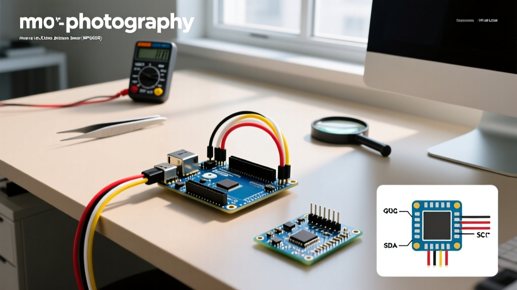
The MPU-6050 communicates via the I2C (Inter-Integrated Circuit) bus. This requires only two data lines, shared across a common ground. Below is the exact pinout for wiring the sensor to an Arduino Uno R4 Minima.
| GY-521 Pin | Arduino Uno R4 Pin | Function & Notes |
|---|---|---|
| VCC | 5V | Powers the onboard LDO regulator. |
| GND | GND | Common ground reference. |
| SCL | A5 (or SCL header) | I2C Clock line. |
| SDA | A4 (or SDA header) | I2C Data line. |
| XDA | Not Connected | Auxiliary I2C master (for external magnetometers). |
| INT | D2 | Interrupt pin (triggers when new data is ready). |
Software Setup: Bypassing Raw Math with the DMP
Reading raw gyroscope data yields values in Least Significant Bits (LSB). At the default full-scale range of ±250 degrees per second (dps), the sensitivity is 131 LSB/°/s. While you can manually divide the raw readings by 131, this ignores temperature drift and sensor noise. The Adafruit MPU6050 learning guide highly recommends utilizing the Adafruit_MPU6050 library, which abstracts the I2C register mapping and provides calibrated data in standard SI units (radians per second for gyro, meters per second squared for the accelerometer).
Core Initialization Code
Install the Adafruit MPU6050 and Adafruit Sensor libraries via the Arduino Library Manager. The following code initializes the sensor, sets the gyroscope range to ±500 dps (ideal for human-motion tracking), and configures the I2C clock to Fast Mode (400kHz) for rapid polling.
#include <Adafruit_MPU6050.h>
#include <Adafruit_Sensor.h>
#include <Wire.h>

Adafruit_MPU6050 mpu;

void setup(void) {
  Serial.begin(115200);
  while (!Serial) delay(10);

  // Initialize I2C bus to 400kHz Fast Mode
  Wire.begin();
  Wire.setClock(400000);

  if (!mpu.begin()) {
    Serial.println("Failed to find MPU6050 chip. Check I2C wiring!");
    while (1) { delay(10); }
  }

  // Set Gyro range to +/- 500 dps for better resolution in robotics
  mpu.setGyroRange(MPU6050_RANGE_500_DEG);
  // Set Accelerometer range to +/- 2G
  mpu.setAccelerometerRange(MPU6050_RANGE_2_G);
  // Set I2C bypass to allow direct access to auxiliary I2C bus
  mpu.setFilterBandwidth(MPU6050_BAND_21_HZ);

  Serial.println("MPU6050 Initialized Successfully.");
}
The Reality of Gyro Drift (And How to Fix It)
A common pitfall for beginners integrating a gyroscope Arduino sensor is integration drift. A gyroscope measures angular velocity (how fast you are turning), not absolute position. To find your current angle, you must mathematically integrate the velocity over time. Because MEMS sensors have inherent bias instability (noise), tiny errors accumulate with every loop iteration. Within 60 seconds, a stationary MPU-6050 might report that it has rotated 5 to 10 degrees.
To solve this, engineers use Sensor Fusion. By combining the short-term accuracy of the gyroscope with the long-term absolute stability of the accelerometer (which uses gravity as a reference), you eliminate drift. The two most common algorithms for this are:
- Complementary Filter: A lightweight math formula that applies a high-pass filter to the gyro and a low-pass filter to the accelerometer. Perfect for basic Arduino projects with limited memory.
- Madgwick or Mahony Filter: Advanced quaternion-based algorithms that calculate 3D orientation (Yaw, Pitch, Roll) without suffering from Gimbal Lock. The Adafruit AHRS (Attitude and Heading Reference System) library implements these natively.
Troubleshooting Matrix: I2C Connection Failures
I2C is a robust protocol, but physical wiring flaws often result in silent failures or bus lockups. Consult this matrix if your Arduino fails to detect the sensor.
| Symptom | Likely Cause | Engineering Fix |
|---|---|---|
| Serial Monitor prints 'Failed to find MPU6050' | Incorrect I2C Address or missing power. | Run the Adafruit I2C Scanner sketch. The default address is 0x68. If the AD0 pin is pulled HIGH, it becomes 0x69. |
| Data reads as all zeros or NaN | I2C bus speed mismatch or weak pull-ups. | Reduce Wire.setClock() back to 100000 (Standard Mode). Cheap GY-521 clones often use 10kΩ pull-ups instead of the recommended 4.7kΩ. |
| Arduino freezes randomly during reads | SDA/SCL lines shorting to ground or VCC. | Check breadboard contacts. Add a 100nF ceramic decoupling capacitor directly across the VCC and GND pins on the breakout board to filter power rail noise. |
Advanced Interfacing: Pushing the I2C Bus
For advanced applications like balancing robots or quadcopter flight controllers, reading the sensor via standard polling introduces latency. The Arduino Wire library documentation details how I2C operates, but to achieve true real-time performance, you should utilize the MPU-6050's INT (Interrupt) pin.
By configuring the sensor's INT_ENABLE register to trigger on 'Data Ready', the sensor will pull the INT pin LOW every time a new sample is written to its internal FIFO buffer (typically at 100Hz to 1kHz). You can attach a hardware interrupt on the Arduino (using attachInterrupt(digitalPinToInterrupt(2), readSensor, FALLING)) to read the data instantly, ensuring your PID control loops receive perfectly timed sensor data without blocking the main loop() function.
Mastering the MPU-6050 bridges the gap between simple blink-LED tutorials and professional-grade embedded systems. By respecting I2C electrical characteristics, implementing sensor fusion to negate drift, and leveraging hardware interrupts, your gyroscope Arduino sensor projects will achieve the precision required for modern robotics and IoT applications.