
The Multi-Peripheral Challenge: Beyond Simple Sensor Reading
Integrating an Arduino magnetic sensor into a standalone test circuit is trivial. However, embedding that same sensor into a multi-peripheral environment—where an I2C OLED display, an SPI SD card logger, and a high-torque servo motor share the same microcontroller—introduces severe timing collisions and electrical noise. When building a precision RPM tachometer or a smart access control system, the magnetic sensor must react in microseconds, while the display and storage peripherals demand milliseconds of bus time. If your architecture relies on polling, your multi-peripheral setup will inevitably drop sensor pulses, resulting in catastrophic data inaccuracies.
In this comprehensive guide, we will engineer a robust, multi-peripheral tachometer. We will cover exact component selection for 2026 supply chains, hardware interrupt topology, I2C bus capacitance management, and advanced EMI mitigation strategies required when placing sensitive Hall effect sensors near inductive loads.
Component Selection & 2026 BOM
Choosing the right magnetic sensor dictates your entire circuit topology. The market has stabilized post-shortage, making precision Hall effect ICs highly accessible and affordable for DIY and prototyping setups.
- Digital Hall Effect Sensor (Allegro A3144EUA-T): Priced around $0.45 per unit on Mouser. This is a unipolar switch with an open-drain output. It triggers cleanly when a specific magnetic flux density threshold is crossed, making it ideal for RPM counting.
- Linear Hall Effect Sensor (Honeywell SS49E): Priced around $1.20. Outputs an analog voltage proportional to the magnetic field. Better for proximity sensing or joystick applications, but requires ADC polling, which we want to avoid in high-speed multi-peripheral setups.
- Microcontroller (Arduino Nano Every): Unlike the classic Nano (ATmega328P), the Nano Every utilizes the ATmega4809. It features a more flexible interrupt architecture and superior I2C buffer management, crucial when sharing the bus with an OLED.
- Display (1.3-inch SH1106 I2C OLED): The SH1106 driver handles internal memory refreshing slightly better than the SSD1306 when I2C bus contention occurs.
The Interrupt Bottleneck: Why Polling Fails
In a multi-peripheral setup, writing a single frame to an I2C OLED display takes approximately 15 to 20 milliseconds. Writing a 512-byte block to an SPI SD card can block the main loop for up to 150 milliseconds. If a magnet on a motor shaft spinning at 3,000 RPM passes your sensor during that blocking window, a polling-based digitalRead() will completely miss the pulse.
To solve this, we must offload pulse detection to the microcontroller's hardware interrupt pins. According to the official Arduino attachInterrupt() documentation, hardware interrupts immediately pause the main program, execute an Interrupt Service Routine (ISR), and resume, ensuring zero missed pulses regardless of I2C or SPI bus traffic.
Wiring Matrix & Pull-Up Topology
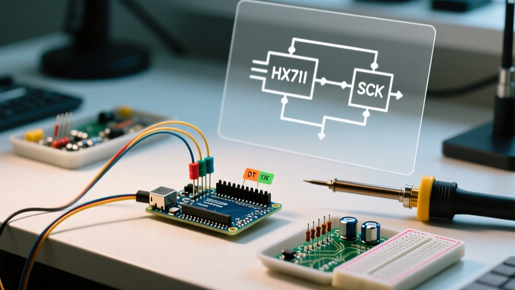
The A3144EUA-T features an open-collector (open-drain) output. This means it can pull the signal line to ground, but it cannot drive it high. You must provide an external pull-up resistor. While the Arduino offers internal pull-ups via INPUT_PULLUP, the internal resistance (typically 20kΩ to 50kΩ) is far too weak for environments with high Electromagnetic Interference (EMI).
| Component | Pin / Function | Arduino Nano Every Pin | Notes & External Components |
|---|---|---|---|
| A3144 Hall Sensor | VCC | 5V | Requires 100nF X7R decoupling cap at pins |
| A3144 Hall Sensor | GND | GND (Analog Ground) | Star-ground to prevent motor ground bounce |
| A3144 Hall Sensor | OUT | D2 (INT0) | 10kΩ external pull-up to 5V; 1kΩ series resistor |
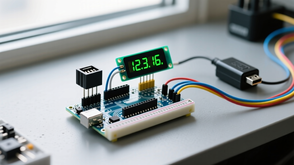
| SH1106 OLED | SDA | A4 (SDA) | 4.7kΩ pull-ups if cable > 10cm |
| SH1106 OLED | SCL | A5 (SCL) | Keep I2C capacitance under 400pF |
| SD Card Module | CS | D10 | SPI bus; use level shifter for 3.3V logic |
Power Integrity & EMI Mitigation
When your Arduino magnetic sensor is mounted near a brushless DC motor or a stepper motor, the inductive kickback and commutator noise will couple into your sensor wiring. This results in 'phantom interrupts'—the microcontroller registering dozens of false RPM spikes.
1. Signal Line Conditioning
Do not run a raw, high-impedance signal wire from the Hall sensor to the Arduino. Place a 1kΩ series resistor on the output line, close to the Arduino's D2 pin. This resistor, combined with the inherent parasitic capacitance of the wire and the microcontroller pin, forms a low-pass RC filter that shaves off high-frequency EMI spikes without delaying the actual magnetic trigger edge.
2. Decoupling and Bypassing
As detailed in SparkFun's comprehensive guide to Hall Effect sensors, magnetic sensor ICs are highly susceptible to VCC rail noise. You must solder a 100nF (0.1µF) X7R ceramic capacitor directly across the VCC and GND pins of the A3144, as physically close to the IC body as possible. This provides a localized high-frequency energy reservoir, preventing voltage sags when the internal output transistor switches.
3. Managing I2C Bus Capacitance
Adding multiple I2C peripherals (OLED, RTC, external EEPROM) increases bus capacitance. The NXP I2C-bus specification (UM10204) strictly limits standard-mode bus capacitance to 400pF. If your ribbon cables are too long, the SDA/SCL rise times will degrade, causing the OLED to freeze when the motor engages. Use twisted-pair wiring for I2C lines and keep total cable runs under 15 centimeters in noisy environments.
Non-Blocking Code Architecture
Writing the firmware for a multi-peripheral tachometer requires strict discipline. The ISR must be as brief as mathematically possible. Never use Serial.print(), delay(), or I2C display updates inside an ISR.
Pro-Tip: Use the
volatilekeyword for any variable shared between the ISR and the main loop. Furthermore, when reading multi-bytevolatilevariables in the main loop, you must temporarily disable interrupts usingnoInterrupts()to prevent data tearing (where the ISR updates the variable halfway through your read operation).
Calculating RPM via Microsecond Deltas
Instead of counting pulses over a fixed one-second window (which introduces terrible latency at low RPMs), measure the time elapsed between individual pulses using the micros() function.
- Inside the ISR, capture the current
micros()value. - Subtract the previous timestamp to find the delta time (
deltaT). - Update the previous timestamp variable.
- Set a
volatile booleanflag totrueto notify the main loop that new data is available.
In the main loop, check the flag. If true, disable interrupts, copy the deltaT to a local variable, re-enable interrupts, and calculate RPM: RPM = 60000000 / deltaT. This yields instantaneous, highly responsive RPM readings that update the OLED smoothly without blocking the SPI SD card logging routines.
Real-World Troubleshooting & Edge Cases
Even with perfect wiring, multi-peripheral setups present unique failure modes. Here is how to diagnose the most common issues encountered in the field.
Edge Case 1: The OLED Freezes at High RPM
Symptom: The tachometer reads accurately up to 1,500 RPM, but at higher speeds, the OLED display locks up or shows corrupted artifacts, while the SD card continues logging correctly.
Root Cause: At high RPMs, the ISR fires so frequently that the main loop is starved of CPU cycles. The I2C Wire library relies on the main loop to process bus acknowledgments. If the ISR consumes more than 80% of the CPU time, the I2C bus times out.
Solution: Implement a software prescaler in your ISR. Only update the timestamp and set the flag on every second or fourth pulse. Alternatively, attach a small neodymium magnet to a secondary, slower-spinning shaft (e.g., a 1:4 gearbox reduction) to reduce the interrupt frequency while maintaining accurate RPM math via multiplication.
Edge Case 2: Ground Bounce Triggering False Reads
Symptom: The moment a relay clicks or a servo motor stalls, the Arduino registers a massive, momentary spike in RPM.
Root Cause: Ground bounce. The high current drawn by the motor travels back through the shared ground wire, momentarily raising the Arduino's ground reference voltage. The Hall sensor's output, referenced to the power supply ground, suddenly appears as a logic LOW to the Arduino, triggering a phantom interrupt.
Solution: Implement a star-ground topology. Run a dedicated, thick-gauge ground wire from the motor driver directly to the power supply's negative terminal. Run a separate ground wire from the Arduino and sensors to the same terminal. Never daisy-chain logic grounds through motor driver ground pins.
Conclusion
Successfully deploying an Arduino magnetic sensor in a multi-peripheral setup requires moving beyond basic tutorials. By leveraging hardware interrupts, enforcing strict power isolation, managing I2C bus capacitance, and writing non-blocking firmware, you transform a fragile prototype into an industrial-grade tachometer or access control system. Whether you are logging brushless motor telemetry or building a complex DIY CNC spindle monitor, these architectural principles ensure your sensor data remains pristine, regardless of what the rest of your peripherals are doing.