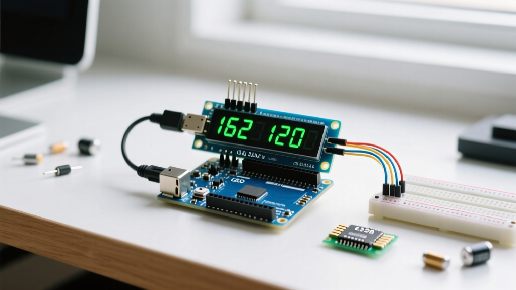

The Evolution of the Arduino Liquid Crystal Display
Interfacing an Arduino liquid crystal display (LCD) remains a cornerstone of embedded systems prototyping in 2026. While OLED and TFT screens have captured the high-resolution market, the classic HD44780-based 16x2 and 20x4 character LCDs persist due to their extreme readability in direct sunlight, low static power draw (typically 20mA with backlight off), and sub-$4.50 module cost. However, the methodology for driving these displays has shifted dramatically. The days of consuming six digital I/O pins for parallel 4-bit communication are over; modern implementations rely almost exclusively on I2C serial backpacks.
This guide dissects the driver architecture, library selection, and low-level I2C communication required to reliably deploy an Arduino liquid crystal display in production-grade DIY projects.
Library Landscape: Choosing the Right Driver
Historically, developers relied on the default LiquidCrystal.h or the ubiquitous LiquidCrystal_I2C.h by Frank de Brabander. Both present significant friction in modern workflows, primarily due to hardcoded I2C addresses and rigid pin-mapping assumptions. The undisputed standard for professional and advanced hobbyist integration is Bill Perry's hd44780 library.
Driver Comparison Matrix
| Library | I2C Auto-Detect | Pin Mapping Flexibility | Execution Speed | Best Use Case |
|---|---|---|---|---|
LiquidCrystal.h | No (Parallel only) | N/A | Fastest (Direct I/O) | Legacy parallel wiring |
LiquidCrystal_I2C.h | No (Hardcoded) | Low (Requires manual hex edits) | Moderate | Quick prototyping |
hd44780.h (I2Cexp) | Yes (Bus scan) | High (Auto-detects PCF8574/MCP23008) | Fast (Asynchronous I2C) | Production & complex I2C buses |
Hardware Architecture: The I2C Backpack
An I2C backpack translates serial data into parallel signals for the HD44780 controller using an I/O expander chip. The two most common expanders are the NXP PCF8574 and PCF8574A. Understanding the difference is critical for avoiding address collisions on multi-device buses.
- PCF8574: Base I2C address is
0x20. With A0, A1, and A2 jumpers bridged (pulled high), the address resolves to0x27. - PCF8574A: Base I2C address is
0x38. With all jumpers bridged, the address resolves to0x3F.
Expert Tip: If you are deploying multiple Arduino liquid crystal display modules on a single I2C bus, intentionally mix PCF8574 and PCF8574A backpacks to guarantee unique addresses without needing to desolder jumper pads or rely solely on the limited A0-A2 permutations.
Wiring and Bus Capacitance
Connect VCC to 5V, GND to GND, SDA to A4 (or dedicated SDA pin), and SCL to A5 (or dedicated SCL). If your I2C bus includes more than three devices or uses cables longer than 30cm, bus capacitance will exceed 200pF, degrading signal rise times. In these scenarios, install 4.7kΩ pull-up resistors on both SDA and SCL lines to ensure crisp logic transitions.
Implementation: Deploying the hd44780 Driver
Using the hd44780 library via the Arduino IDE Library Manager, the initialization sequence requires minimal boilerplate while maximizing hardware compatibility.
#include <Wire.h>
#include <hd44780.h>
#include <hd44780ioClass/hd44780_I2Cexp.h>

// Auto-detects I2C address and backpack pin mapping
hd44780_I2Cexp lcd;

void setup() {
  // Initialize 16x2 display
  lcd.begin(16, 2);
  lcd.print("System Online");
  lcd.setCursor(0, 1);
  lcd.print("Flux OS v2.4");
}

void loop() {}
Advanced Peripheral Control: CGRAM Custom Characters
The HD44780 controller features 64 bytes of Character Generator RAM (CGRAM), allowing you to define up to eight custom 5x8 pixel characters. This is essential for rendering battery indicators, signal strength bars, or proprietary brand icons that the standard ASCII ROM set lacks.
Designing a Custom Thermometer Icon
Map your pixels using a binary array where 1 represents an illuminated pixel and 0 is blank. Note that the lowest bit of each byte is ignored by the hardware controller.
byte thermometer[8] = {
  B00100,
  B01010,
  B01010,
  B01010,
  B01110,
  B11111,
  B11111,
  B01110
};

// In setup():
lcd.createChar(0, thermometer);
// In loop():
lcd.setCursor(0, 0);
lcd.write((byte)0); // Cast to byte to avoid compiler overload conflicts
Troubleshooting Edge Cases and Failure Modes
Even with robust drivers, physical layer anomalies frequently disrupt Arduino liquid crystal display integrations. Use this diagnostic matrix to resolve common deployment failures.
1. Top Row Displays Solid White Blocks
Root Cause: The HD44780 has initialized its internal memory, but the MCU is failing to transmit I2C data. This is almost always an address mismatch or missing pull-up resistors.
Resolution: Run an I2C scanner sketch. If the device does not appear at 0x27 or 0x3F, check for cold solder joints on the backpack's 16-pin header.
2. Ghosting or Extremely Dim Characters
Root Cause: Improper V0 (contrast) voltage. The LCD requires the V0 pin to sit between 0.4V and 0.8V relative to GND for optimal liquid crystal alignment.
Resolution: The backpack includes a 10KΩ trimpot. Turn it counter-clockwise slowly. It often requires 15 to 20 full rotations before the contrast voltage drops into the visible threshold.
3. Garbage Characters on 3.3V Microcontrollers
Root Cause: Driving a 5V LCD module with a 3.3V MCU (like the ESP32 or SAMD21) violates the HD44780 logic high threshold (Vih), which typically requires 0.7 x VDD (approx 3.5V).
Resolution: Insert a bidirectional logic level shifter (e.g., BSS138-based modules) between the MCU and the I2C backpack, or power the LCD VCC with 3.3V (note: this will severely dim the LED backlight unless you bypass the backpack onboard 5V regulator).
Engineering Note: When integrating an Arduino liquid crystal display into battery-powered IoT nodes, remember that the LED backlight consumes 80% of the module power. Wire the backlight Anode (often pin 15 on the backpack) to a MOSFET-controlled PWM pin, allowing your firmware to extinguish the backlight during idle states, dropping the display power draw from ~60mA down to ~1.5mA.


