
The Core Challenge: Merging Sensor Logic with High-Current Actuation
Bridging the gap between low-voltage sensor data and high-current motor actuation is a fundamental rite of passage in robotics and automation. While blinking an LED based on sensor input is trivial, driving inductive loads like DC motors requires careful isolation, power management, and timing. In 2026, despite the proliferation of modern MOSFET-based drivers, the arduino motor controller l298n remains a staple in educational and prototyping environments due to its rugged high-voltage tolerance (up to 35V) and accessible through-hole or module-based packaging.
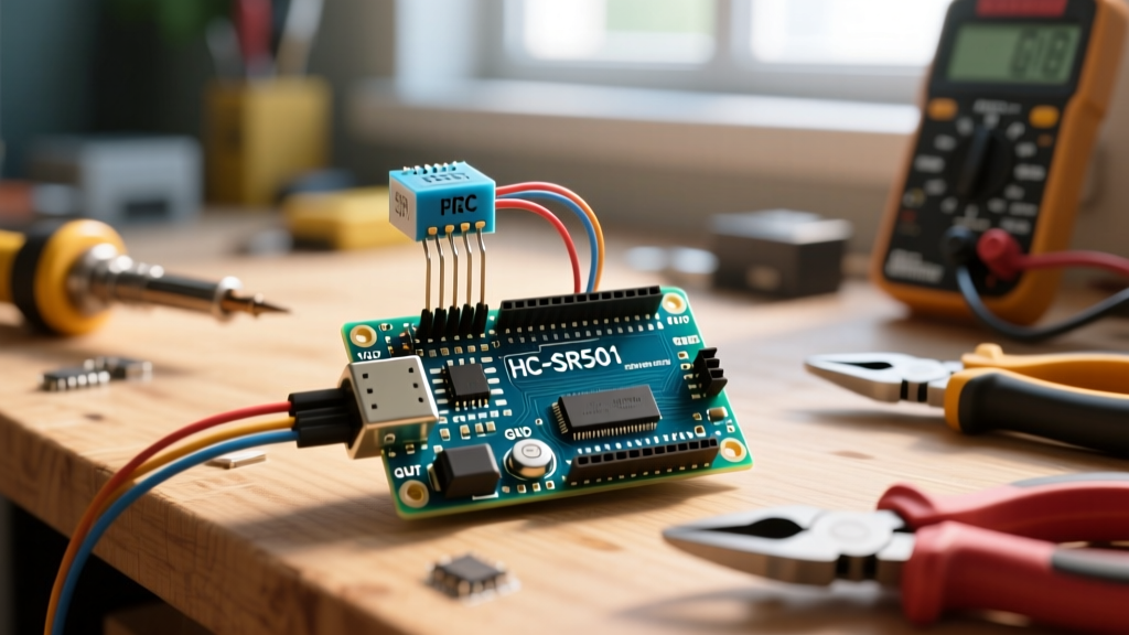
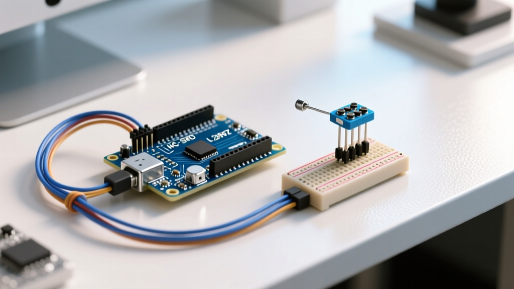
This tutorial moves beyond basic 'spin a motor' guides. We will integrate an HC-SR04 ultrasonic sensor with the L298N dual H-bridge to create a closed-loop, proportional control system. The motor's speed and direction will dynamically scale based on real-time proximity data, requiring a deep understanding of PWM mapping, microsecond timing, and shared-ground topologies.
Hardware Anatomy: L298N and HC-SR04 Specifications
To design a reliable circuit, you must understand the physical limitations of your components. The L298N is not a modern, high-efficiency MOSFET driver; it relies on internal Bipolar Junction Transistor (BJT) Darlington pairs. This architecture introduces a significant voltage drop and thermal overhead that must be accounted for in your power budget.
| Parameter | L298N Dual H-Bridge Module | HC-SR04 Ultrasonic Sensor |
|---|---|---|
| Operating Voltage | 5V (Logic), 5V-35V (Motor) | 5V DC (Logic & Power) |
| Current Draw | Up to 2A per channel (3A peak) | 15mA (Active), 2mA (Idle) |
| Voltage Drop | ~2.0V (BJT Saturation) | N/A |
| Control Interface | 2x Direction Pins, 1x PWM Enable | 1x Trigger (Input), 1x Echo (Output) |
| Average 2026 Cost | $3.50 - $5.00 USD | $1.50 - $2.50 USD |
According to the STMicroelectronics L298N datasheet, the 2V voltage drop across the internal BJT junctions means that if you supply 12V to the VCC terminal, your motor will only receive approximately 10V. Furthermore, at a continuous 2A draw, the IC will dissipate roughly 4 Watts of heat (2V × 2A), making the attached aluminum heatsink mandatory to prevent thermal shutdown.
Wiring Matrix: Pinout and Power Distribution
The most common point of failure in sensor-motor integration is improper power distribution and floating grounds. When an Arduino motor controller l298n switches high currents, it creates severe electromagnetic interference (EMI) and ground bounce, which can corrupt the sensitive 5V logic signals returning from the HC-SR04 sensor.
Critical Warning: Never power the HC-SR04 and the L298N's 5V logic rail from the Arduino's onboard 5V regulator if your motors draw more than 500mA. The inrush current from the motors will cause a voltage sag, resetting the Arduino's microcontroller (ATmega328P or similar). Use a dedicated 5V buck converter (like an LM2596 module) to supply the sensor and logic rails.
Step-by-Step Wiring Guide
- Motor Power (12V): Connect a 12V DC power supply to the L298N's
12VandGNDscrew terminals. Ensure the 5V-EN jumper on the module is removed if your input voltage exceeds 12V to protect the onboard 7805 linear regulator. - Common Ground: Connect the GND of the 12V power supply, the L298N GND, the Arduino GND, and the HC-SR04 GND together. A single, unified ground plane is non-negotiable for stable PWM and sensor readings.
- Motor Outputs: Connect Motor A to
OUT1andOUT2. Connect Motor B toOUT3andOUT4. - Logic Control: Connect
IN1andIN2to Arduino digital pins 8 and 9. ConnectENA(Enable A) to Arduino Pin 10 (a hardware PWM capable pin). - Sensor Integration: Connect HC-SR04
VCCto 5V,GNDto common ground,Trigto Arduino Pin 11, andEchoto Arduino Pin 12.
Sensor-Driven Control Logic (The Code Architecture)
To achieve proportional control, we must translate the HC-SR04's time-of-flight data into a usable distance metric, and then map that metric to a PWM duty cycle. The HC-SR04 emits a 40kHz ultrasonic burst when the Trigger pin is held HIGH for 10 microseconds. The Echo pin then goes HIGH for a duration proportional to the distance the sound traveled.
Implementing Proportional Distance Mapping
Sound travels at approximately 343 meters per second in dry air at 20°C. This equates to roughly 29.1 microseconds per centimeter for a one-way trip. Because the ultrasonic pulse must travel to the object and back, we divide the total time by 58.2 to get the distance in centimeters.
// Pin Definitions
const int trigPin = 11;
const int echoPin = 12;
const int in1 = 8;
const int in2 = 9;
const int enA = 10;

void setup() {
  pinMode(trigPin, OUTPUT);
  pinMode(echoPin, INPUT);
  pinMode(in1, OUTPUT);
  pinMode(in2, OUTPUT);
  pinMode(enA, OUTPUT);
  Serial.begin(9600);
}

void loop() {
  // 1. Trigger Ultrasonic Burst
  digitalWrite(trigPin, LOW);
  delayMicroseconds(2);
  digitalWrite(trigPin, HIGH);
  delayMicroseconds(10);
  digitalWrite(trigPin, LOW);

  // 2. Read Echo and Calculate Distance
  long duration = pulseIn(echoPin, HIGH);
  float distance_cm = duration / 58.2;

  // 3. Map Distance to PWM (Proportional Control)
  // If distance is > 100cm, full speed (255).
  // If distance is < 20cm, stop (0) and reverse.
  int motorSpeed = 0;

  if (distance_cm >= 100) {
    motorSpeed = 255;
    setMotorDirection('FORWARD');
  } else if (distance_cm > 20 && distance_cm < 100) {
    motorSpeed = map(distance_cm, 20, 100, 50, 255);
    setMotorDirection('FORWARD');
  } else if (distance_cm <= 20) {
    motorSpeed = 150;
    setMotorDirection('REVERSE');
  }

  analogWrite(enA, motorSpeed);
  delay(50); // Sensor settling time
}

void setMotorDirection(char dir) {
  if (dir == 'FORWARD') {
    digitalWrite(in1, HIGH);
    digitalWrite(in2, LOW);
  } else {
    digitalWrite(in1, LOW);
    digitalWrite(in2, HIGH);
  }
}
By utilizing the map() function, the Arduino motor controller l298n receives a dynamically scaled PWM signal. As an object approaches the sensor, the motor smoothly decelerates, stops at the 20cm threshold, and reverses to avoid a collision. This mimics the proportional (P) component of a PID controller, providing much smoother mechanical actuation than binary on/off switching.
Real-World Failure Modes and Troubleshooting
Even with perfect code, physical hardware introduces edge cases. According to Arduino's official motor electronics documentation, inductive kickback and power rail noise are primary culprits in erratic system behavior. Below are specific failure modes you will encounter and how to resolve them.
1. The 'Whining Motor' Phenomenon
Symptom: The motor emits a high-pitched whine but fails to rotate, especially at low PWM values (below 80).
Root Cause: The L298N's BJT transistors require a minimum threshold voltage to overcome the motor's static friction (stall torque). Furthermore, the default Arduino PWM frequency on pins 9 and 10 is ~490Hz. At low duty cycles, the effective voltage drops below the motor's operational threshold.
Fix: Implement a 'deadband' in your code. If the calculated PWM is below 80, force it to 0. Alternatively, alter the Arduino's timer registers to increase the PWM frequency to ~31kHz, moving the whine out of the human hearing range and providing sharper switching edges.
2. Sensor Ghost Readings During Motor Spin
Symptom: The HC-SR04 returns random '0' or '3000cm' values exactly when the motor changes direction.
Root Cause: Back-EMF (Electromotive Force) generated by the motor's inductive coils during braking feeds back into the power rail, causing microsecond voltage spikes that corrupt the HC-SR04's echo timing.
Fix: While most L298N modules include 1N4007 flyback diodes across the output terminals, they are often too slow (standard recovery) to clamp high-frequency spikes. Soldering 100nF ceramic capacitors directly across the motor terminals (at the motor casing, not the driver board) will drastically reduce high-frequency EMI.
3. Logic Brownouts and Arduino Resets
Symptom: The Arduino resets or freezes when the motor starts under load.
Root Cause: The motor's inrush current (which can be 5x to 10x its running current) pulls the shared 12V rail down. If you are using the L298N module's onboard 7805 linear regulator to power the Arduino, this voltage sag drops the 5V logic rail below the ATmega328P's brownout detection threshold (typically 4.3V).
Fix: Never rely on the L298N's onboard 5V regulator for the main microcontroller. Power the Arduino via its USB port or a separate, high-current 5V buck converter. For a deeper dive into module specifications and internal schematics, Components101's L298N breakdown provides excellent visual references for the onboard jumper configurations.
Modern Alternatives vs. The L298N (2026 Perspective)
While mastering the arduino motor controller l298n is an excellent exercise in understanding BJT H-bridges and basic power electronics, modern designs in 2026 often favor MOSFET-based alternatives for battery-powered applications. Drivers like the TB6612FNG or the DRV8871 exhibit a voltage drop of merely 0.2V to 0.5V, compared to the L298N's massive 2.0V drop. This translates to vastly superior battery life and eliminates the need for bulky heatsinks. However, the L298N's ability to safely handle up to 35V and its extreme tolerance to wiring mistakes keep it relevant for heavy-duty, non-battery-constrained prototyping.