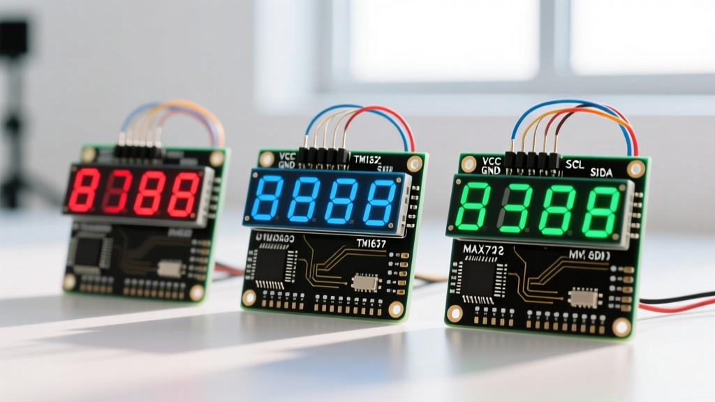

The Evolution of Arduino Seven Segment Display Integration
When building digital clocks, scoreboards, or sensor readouts, the classic seven-segment display remains a staple in electronics. However, the days of manually wiring 14 pins and writing complex multiplexing timers are largely behind us. If you are planning an arduino seven segment display project in 2026, you are likely choosing between three distinct hardware paths: bare displays with direct GPIO multiplexing, the budget-friendly TM1637 driver modules, and the premium MAX7219 SPI-based modules.
As the maker ecosystem has shifted heavily toward 3.3V microcontrollers like the ESP32-S3 and Raspberry Pi Pico (RP2040), the electrical characteristics of these display drivers matter more than ever. This guide provides a deep-dive engineering comparison to help you select the right display architecture for your specific power, pin-count, and logic-level constraints.
Contender 1: Bare 4-Digit Displays (Direct Multiplexing)
The bare 4-digit common cathode (or common anode) display is the most rudimentary option. Typically featuring a 12-pin DIP package, it requires you to manually wire current-limiting resistors (usually 220Ω to 330Ω) to the segment pins and handle the multiplexing in your firmware.
Wiring Realities and the 'Flicker' Trap
To display four distinct digits, your microcontroller must cycle through the four common pins rapidly (typically at >100Hz) while updating the segment pins for each digit. While this saves money (bare displays cost around $1.20 to $1.80), it consumes 12 GPIO pins and requires constant CPU attention.
- The Flicker Trap: If your main Arduino loop includes blocking functions like
delay()or long I2C sensor reads, the multiplexing timer interrupts, causing visible flickering or ghosting. - Current Limits: Sourcing current directly from ATmega328P or ESP32 GPIO pins can exceed the per-pin maximum rating (often 20mA-40mA) if multiple segments are illuminated simultaneously without proper transistor switching on the common pins.
Contender 2: TM1637 Modules (The Budget I2C-Like Driver)
The TM1637 module (typically priced between $2.50 and $3.50) is the undisputed king of budget Arduino projects. It reduces the wiring to just four pins: VCC, GND, DIO, and CLK. However, a critical misconception in the maker community is that the TM1637 uses standard I2C. It does not. It uses a proprietary two-wire serial protocol that merely resembles I2C.
The 3.3V Logic Level Pitfall
According to the Titan Micro Electronics datasheet, the TM1637 is designed for 5V operation. The high-level input voltage (VIH) threshold is typically 0.7 × VDD. If VDD is 5V, the microcontroller must output at least 3.5V for the TM1637 to reliably register a logic HIGH.
Engineering Warning: If you are using a 3.3V microcontroller (like an ESP32 or RP2040), the 3.3V output falls below the 3.5V threshold. While some modules might 'work' due to silicon tolerances, this leads to intermittent data corruption and ghost digits in high-EMI environments. For 3.3V systems, you must use a bidirectional logic level shifter (like the BSS138 or CD4050) or switch to the MAX7219.
For standard 5V Arduino Uno or Nano boards, the TM1637Display library by Avishay Orpaz provides a robust, non-blocking API that handles the proprietary protocol flawlessly.
Contender 3: MAX7219 Modules (The SPI Powerhouse)
The MAX7219 (originally designed by Maxim Integrated, now Analog Devices) is a true hardware multiplexer utilizing the standard Serial Peripheral Interface (SPI). Priced higher at $5.00 to $8.50 per module, it offers professional-grade features that the TM1637 simply cannot match.
Daisy Chaining and Hardware Current Control
Unlike the TM1637, the MAX7219 requires zero external current-limiting resistors for the LEDs. Instead, you place a single resistor (typically 10kΩ to 27kΩ) on the ISET pin, and the internal DAC scales the current for all 64 LEDs automatically. Furthermore, the MAX7219 features a native DOUT (Data Out) pin, allowing you to daisy-chain dozens of modules using only three microcontroller pins (DIN, CS, CLK).
- 3.3V Compatibility: The MAX7219 has a much more forgiving logic threshold. With a 5V VCC, a logic HIGH is guaranteed at 3.5V, but it often reliably triggers at 3.3V, making it vastly superior for modern ESP32 and ARM Cortex integrations.
- Library Support: The
LedControllibrary or the more modernMAX72xxParola libraries allow for complex scrolling text and hardware-level brightness PWM without touching the main CPU loop.
Head-to-Head Comparison Matrix
| Feature | Bare Display (Direct) | TM1637 Module | MAX7219 Module |
|---|---|---|---|
| Microcontroller Pins Used | 12 (or 8 with shift register) | 4 (2 data) | 5 (3 data) |
| Communication Protocol | Direct GPIO / Timers | Proprietary 2-Wire | Standard SPI |
| Native 3.3V Logic Support | Yes | No (Requires Level Shifter) | Yes (Mostly compatible) |
| External Resistors Needed | Yes (8x 220Ω) | No (Built-in) | No (1x ISET Resistor) |
| Daisy-Chaining | No | No | Yes (Virtually Unlimited) |
| Approximate Cost (2026) | $1.20 - $1.80 | $2.50 - $3.50 | $5.00 - $8.50 |
| CPU Overhead | High (Timer Interrupts) | Low | Very Low (Hardware SPI) |
Power Budgeting: Real-World Current Draw
When designing battery-operated sensor nodes, understanding the quiescent and active current draw of your display is critical.
- Bare Displays: Current draw fluctuates wildly depending on the number of illuminated segments. Displaying '8888' can pull upwards of 160mA if not properly multiplexed, but drops significantly when displaying '1111'.
- TM1637: The IC itself draws about 2mA to 5mA in active mode. However, it supports a software-controlled sleep mode via the
setBrightness(0, false)command, dropping total module consumption to under 1mA, making it viable for low-power sleep-wake cycles. - MAX7219: The MAX7219 includes a dedicated hardware shutdown pin and a software shutdown register. In shutdown mode, the display blanks, and the IC's quiescent current drops to roughly 150µA, though the SPI bus must remain active to wake it.
Final Verdict: Which Driver Should You Choose?
The 'best' Arduino seven segment display setup depends entirely on your microcontroller ecosystem and project scale.
Choose the TM1637 if you are building a simple, low-cost 5V Arduino Uno project (like a basic digital clock or temperature readout) and only need a single 4-digit module. It is cheap, ubiquitous, and requires minimal wiring.
Choose the MAX7219 if you are using a 3.3V microcontroller (ESP32, RP2040, STM32), need to daisy-chain multiple displays for a large scoreboard, or require precise, hardware-managed brightness control without CPU overhead. The extra $3 per module is easily justified by the elimination of logic-level shifters and the robust SPI architecture.
Avoid Bare Displays unless you are intentionally trying to learn the fundamentals of multiplexing, timer interrupts, and transistor switching for educational purposes.
Frequently Asked Questions
Can I use a TM1637 display with an ESP32 without a logic level shifter?
While some users report success by powering the TM1637 with 3.3V (which lowers the VIH threshold to ~2.3V), the display will be noticeably dimmer. If you power it with 5V for full brightness, the 3.3V ESP32 GPIO pins may fail to reliably trigger the CLK and DIO lines, leading to random numbers on the screen. A dedicated logic level shifter is highly recommended.
Why do my MAX7219 displays show random garbage characters on startup?
The MAX7219 does not have an internal power-on reset circuit. When power is applied, the internal registers are in an undefined state. You must explicitly send a command to clear the display and take the IC out of shutdown mode in your setup() function immediately after boot.
What is the maximum wire length for these displays?
For the TM1637, keep the DIO and CLK wires under 30cm (12 inches) to avoid capacitive coupling and signal degradation. The MAX7219, utilizing SPI, can handle slightly longer runs (up to 50cm) if you use twisted pair wiring for GND and CLK, but for distances over 1 meter, consider using differential line drivers like the RS-422 standard.