
Beyond the Breadboard: Scaling Up Motor Control
Transitioning from desktop prototypes to field-deployed robotics exposes the harsh realities of power electronics. When integrating an Arduino H bridge motor driver into a heavy-duty rover, automated winch, or solar tracker, the margin for error shrinks dramatically. A stalled motor drawing 25 amps will instantly vaporize hobbyist traces and fry logic circuits if the system lacks proper isolation, thermal mass, and firmware-level dead-time.
This guide bypasses basic tutorials and dives into the electrical engineering realities of deploying high-current H-bridges in 2026, focusing on the widely available BTS7960 43A module, advanced PWM tuning, and critical failure mode mitigation.
The BJT Bottleneck: Why Standard Modules Fail in the Field
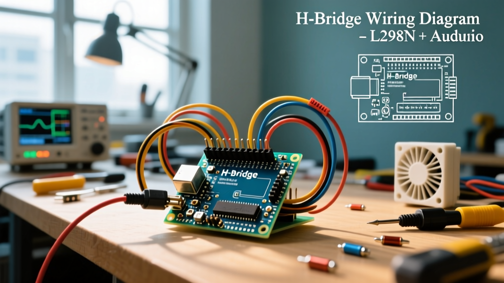
The ubiquitous L298N dual H-bridge is a staple in educational kits, but it is fundamentally unsuited for real-world continuous loads. The L298N relies on Bipolar Junction Transistors (BJTs). BJTs suffer from a high saturation voltage drop—typically 2.0V to 3.0V across the bridge.
Thermal Reality Check: At a modest 2A continuous draw, a 2.5V drop results in 5W of wasted heat per channel. Push this to 5A, and you are dissipating 12.5W, requiring massive, actively cooled heatsinks just to prevent thermal shutdown.
Modern industrial applications demand MOSFET-based drivers. According to Infineon's motor control IC guidelines, modern half-bridge MOSFETs offer an RDS(on) in the milliohm range, shifting the thermal burden from silicon junctions to the PCB copper and external heatsinks.
2026 High-Power Driver Comparison Matrix
When sourcing an Arduino H bridge motor driver for loads exceeding 5A, you must evaluate continuous current limits, logic isolation, and switching speeds. Below is a field-tested comparison of the most prevalent high-power modules available today.
| Module / IC | Topology | Continuous Current | Voltage Range | Logic Isolation | Est. Price (2026) |
|---|---|---|---|---|---|
| L298N | BJT | 2A (3A peak) | 5V - 35V | Optocoupler (Optional) | $4 - $7 |
| DRV8871 | MOSFET | 3.6A | 6.5V - 45V | None (Direct Logic) | $8 - $12 |
| BTS7960 (IBT-2) | MOSFET | 25A (43A peak) | 5.5V - 27V | Optocoupler (Built-in) | $14 - $18 |
| Cytron MD30C | MOSFET | 30A | 5V - 30V | Direct Logic | $35 - $45 |
For high-torque 12V/24V applications, the BTS7960 remains the undisputed price-to-performance king, provided you address its notorious clone-manufacturing quirks.
Heavy-Duty Wiring Protocol: Star Grounding and Gauge Selection
The most common cause of microcontroller resets in motor circuits is ground bounce. When a 20A inductive load switches off, the collapsing magnetic field forces current back into the power rails. If your Arduino shares a thin ground wire with the motor's return path, the voltage spike will momentarily lift the MCU's ground reference above its logic threshold, causing a brownout reset.
1. Power Wiring and Ferrules
Never use standard Dupont jumper wires for motor power. For a 20A continuous load, use 10 AWG silicone-insulated wire. More importantly, terminate these wires with crimped ferrules before inserting them into the BTS7960 screw terminals. Stranded wire splayed inside a screw terminal creates high-resistance contact points that will melt under sustained 20A loads.
2. Implementing a Star Ground Topology
Route the high-current motor ground directly from the power supply to the H-bridge motor terminal. Create a separate, dedicated ground wire from the power supply to the Arduino's GND pin. These two ground paths should only meet at a single physical point (the power supply terminal or a heavy-duty busbar). This 'star ground' ensures that high-current transients never flow through the microcontroller's ground plane.
3. Logic Level Shifting and Isolation
The BTS7960 module features onboard optocouplers, but they require a separate logic voltage. Connect the module's VCC pin to the Arduino's 5V output, but remove the jumper that ties the motor logic to the onboard 5V regulator if your specific board variant has one. As detailed in the Arduino analogWrite documentation, ensuring clean logic signals is paramount for stable PWM generation.
Advanced PWM Tuning: Eliminating Audible Whine and Shoot-Through
By default, the Arduino Uno and Nano generate PWM signals at approximately 490Hz on most pins. When applied to a high-power H-bridge, this low frequency falls squarely in the human audible range, causing the motor and inductors to emit a high-pitched whine. Furthermore, 490Hz is inefficient for modern MOSFETs, leading to excessive switching losses in the transition regions.
Shifting Timer1 to 31.37 kHz
To achieve silent operation and optimal switching efficiency, we must push the PWM frequency above 20kHz. On the ATmega328P, pins 9 and 10 are controlled by Timer1. We can modify the Timer1 prescaler via direct register manipulation in the setup() function.
void setup() {
  // Set pins 9 and 10 as outputs
  pinMode(9, OUTPUT);  // RPWM
  pinMode(10, OUTPUT); // LPWM

  // Clear Timer1 control registers
  TCCR1A = 0;
  TCCR1B = 0;

  // Set Fast PWM mode, non-inverting
  TCCR1A |= (1 << COM1A1) | (1 << COM1B1) | (1 << WGM11);

  // Set prescaler to 1 (31.37 kHz frequency) and enable Fast PWM
  TCCR1B |= (1 << WGM13) | (1 << WGM12) | (1 << CS10);

  // Set top value for 8-bit resolution (0-255)
  ICR1 = 255;
}
This configuration yields a 31.37kHz PWM frequency, rendering the motor completely silent and drastically reducing EMI interference with onboard sensors like LiDAR or ultrasonic rangefinders.
Software Dead-Time Insertion
When reversing motor direction, the firmware must turn off one set of MOSFETs before turning on the other. If both the high-side and low-side MOSFETs on the same leg conduct simultaneously—even for a microsecond—it creates a 'shoot-through' condition, effectively shorting the battery directly to ground. While quality H-bridge ICs have hardware dead-time, cheap clone modules often lack it. Always insert a 10-millisecond delay in your code when crossing the zero-speed threshold.
Real-World Failure Modes and Troubleshooting
Even with perfect wiring, field deployments introduce environmental variables that destroy poorly protected circuits. Consult Texas Instruments' motor driver application notes for deep-dives into inductive kickback, but here are the three most common field failures:
- Missing Flyback Diodes on Clone Modules: The official BTS7960 datasheet specifies external Schottky flyback diodes to clamp inductive voltage spikes. Many $12 clone modules omit these to save costs. Fix: Solder 10A Schottky diodes (like the 10SQ050) across the motor terminals, with the cathode facing the positive rail.
- Thermal Throttling at 30A: The BTS7960 is rated for 43A peak, but continuous 30A without active airflow will trigger the IC's internal thermal shutdown at 110°C. Fix: Mount a 40mm 12V fan directly over the TO-220 packages, or upgrade to an IBT-2 variant with an integrated aluminum fin heatsink.
- Optocoupler LED Burnout: Driving the optocoupler input pins directly from a 5V Arduino pin without a current-limiting resistor will degrade the internal LEDs over time, leading to erratic switching. Fix: Verify if your specific module has onboard SMD resistors. If not, add 220Ω resistors in series with the RPWM and LPWM logic lines.
Final Field-Testing Checklist
Before deploying your Arduino H bridge motor driver into an autonomous chassis, perform a staged load test. Run the motor at 25% duty cycle with a multimeter clamped around the main power lead to verify baseline current. Gradually increase to 100% while monitoring the H-bridge temperature with an infrared thermometer. If the IC casing exceeds 70°C under normal operating loads, your mechanical gearing is too high, or your heatsinking is insufficient. True engineering is not just making the motor spin; it is ensuring it survives the environment.