
The Reality of High-Torque Actuation in Modern Robotics
Transitioning from blinking LEDs to moving physical mass is a major milestone in electronics. When it comes to coding servo arduino setups for real-world applications like 3D-printed robotic arms, camera gimbals, or automated sorting gates, the standard tutorial code falls dangerously short. In 2026, while smart serial bus servos are becoming more accessible, standard PWM (Pulse Width Modulation) hobby servos like the TowerPro MG996R (typically $10–$14) and the Futaba S3003 ($15–$18) remain the undisputed backbone of prototyping due to their cost-to-torque ratio.
However, simply importing the default Servo.h library and running the basic sweep.ino sketch will result in violent mechanical snapping, gear stripping, and microcontroller brownouts. True precision requires a deep understanding of non-blocking code execution, power delivery physics, and microsecond-level PWM calibration.
Power Delivery: Why Your Arduino Keeps Resetting
The most common point of failure when coding servo Arduino projects isn't the software; it is the power architecture. A standard Arduino Uno utilizes an onboard linear voltage regulator (often the NCP1117) that safely provides roughly 800mA of current at 5V. An MG996R servo, which boasts 13kg-cm of torque, draws about 500mA at idle but can spike to 2.5 Amps during stall or rapid acceleration.
If you power a high-torque servo directly from the Arduino’s 5V pin, the voltage will instantly sag below the ATmega328P’s brownout detection threshold (usually 2.7V to 4.3V), causing the microcontroller to reset mid-cycle. This results in the dreaded 'servo jitter dance' and can corrupt your EEPROM.
The BEC Solution and Decoupling
To solve this, you must use a dedicated BEC (Battery Eliminator Circuit). A 6V 3A switching BEC (such as the Turnigy 5A, costing around $8) connected directly to a 2S or 3S LiPo battery is the industry standard for hobbyist robotic arms.
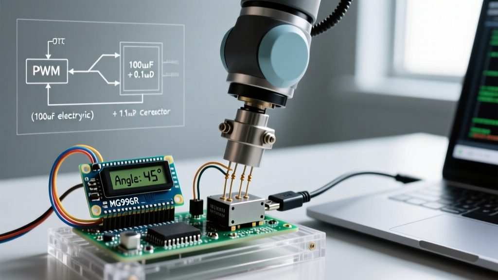
Pro-Tip: Even with a dedicated BEC, long power wires introduce inductance. Always solder a 470µF electrolytic capacitor in parallel with a 0.1µF ceramic capacitor directly across the 6V and GND terminals at the servo end. This local energy reservoir absorbs the microsecond current spikes during PWM switching, completely eliminating high-frequency jitter.
Crucially, you must tie the BEC ground, the servo ground, and the Arduino ground together. Without a common ground reference, the PWM signal wire has no return path, and the servo will behave erratically or not move at all. For a deeper dive into the electrical characteristics of these actuators, refer to Pololu's comprehensive RC servo guide, which details the internal potentiometer feedback loops and current draw curves.
Beyond Sweep: Non-Blocking Code and Kinematic Easing
The default delay() function used in basic Arduino tutorials halts the entire microcontroller. In a multi-joint robotic arm, blocking code means you cannot read limit switches, process inverse kinematics, or monitor battery voltage while a joint is moving.
Furthermore, moving a servo from 0° to 180° at maximum speed generates massive inertial forces. If your robotic arm is holding a 200g payload, the sudden stop at 180° can shear 3D-printed PLA brackets or strip the internal brass gears of the servo.
Implementing Cosine Interpolation
To achieve fluid, professional-grade motion, we use millis() for non-blocking timing and a cosine easing function. This mathematical approach accelerates the servo smoothly out of the starting position and decelerates it gently into the target position, mimicking the natural motion profiles of industrial stepper-driven SCARA arms.
#include <Servo.h>

Servo shoulderJoint;
const int servoPin = 9;

// Motion parameters
int startPos = 500;   // Microseconds (approx 0 deg)
int endPos = 2400;    // Microseconds (approx 180 deg)
long moveDuration = 2000; // 2 seconds for smooth travel
long startTime = 0;
bool isMoving = false;

void setup() {
  shoulderJoint.attach(servoPin, 500, 2400);
  shoulderJoint.writeMicroseconds(startPos);
  startTime = millis();
  isMoving = true;
}

void loop() {
  if (isMoving) {
    long currentTime = millis() - startTime;
    if (currentTime < moveDuration) {
      // Cosine easing: maps 0.0 to 1.0 smoothly
      float progress = (1.0 - cos((float)currentTime / moveDuration * PI)) / 2.0;
      int currentPos = startPos + (endPos - startPos) * progress;

      // writeMicroseconds offers 10x the resolution of write()
      shoulderJoint.writeMicroseconds(currentPos);
    } else {
      shoulderJoint.writeMicroseconds(endPos);
      isMoving = false; // Movement complete, CPU is now free
    }
  }

  // CPU is free to run inverse kinematics, read sensors, or handle serial comms here
}
By utilizing writeMicroseconds() instead of the standard write() degree function, you bypass the library's internal degree-to-microsecond mapping, granting you direct access to the timer hardware. This is vital for precision calibration, as detailed in the official Arduino Servo library reference.
Real-World PWM Calibration Matrix
The theoretical PWM range for RC servos is 1000µs (0°) to 2000µs (180°). In reality, manufacturing tolerances, potentiometer dead-bands, and gear backlash mean that no two servos are exactly alike. Sending a 1000µs pulse to an MG996R often forces the motor against its internal hard stop, causing it to draw stall current continuously, overheat, and drain your battery.
Before finalizing your code, you must manually map the physical limits of your specific servo. Use a potentiometer connected to an analog pin to sweep the pulse width and note the exact microsecond values where the servo stops moving without audibly straining.
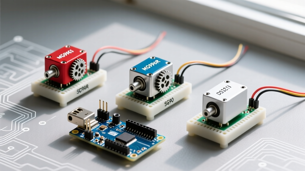
| Servo Model | Theoretical Min (0°) | Actual Safe Min | Theoretical Max (180°) | Actual Safe Max | Deadband Width |
|---|---|---|---|---|---|
| TowerPro MG996R | 1000 µs | 540 µs | 2000 µs | 2420 µs | ~8 µs |
| Futaba S3003 | 1000 µs | 900 µs | 2000 µs | 2100 µs | ~15 µs |
| Hiwonder DS3218 (PWM Mode) | 1000 µs | 650 µs | 2000 µs | 2350 µs | ~4 µs |
| SG90 (Micro 9g) | 1000 µs | 500 µs | 2000 µs | 2400 µs | ~20 µs |
Notice the 'Deadband Width'. This is the minimum change in pulse width required for the servo's internal comparator to register a position change. If your code updates the servo position by increments smaller than the deadband, the servo will simply ignore the command, leading to cumulative positioning errors in multi-axis arms.
Mechanical and Electrical Failure Modes
Even with perfect code and robust power, real-world environments introduce variables that can degrade performance. Understanding these failure modes is what separates a weekend hobbyist from a robotics engineer.
1. Signal Wire Crosstalk and EMI
Routing thin, unshielded PWM signal wires parallel to high-current stepper motor cables or switching power supply lines will induce Electromagnetic Interference (EMI). The ATmega328P outputs a clean 5V square wave, but by the time it reaches the servo 12 inches away, inductive coupling may have introduced voltage spikes. The servo interprets these spikes as microsecond-level position changes, causing high-frequency buzzing. Solution: Use twisted-pair wiring for signal and ground, or route a dedicated ground wire alongside every PWM signal wire.
2. Potentiometer Wear and Jitter
Standard analog servos rely on an internal carbon-track potentiometer for position feedback. After 50 to 100 hours of continuous oscillation (common in active suspension or balancing robots), the carbon track wears down, introducing electrical noise. The servo's internal op-amp reads this noise as positional drift and attempts to correct it, resulting in violent oscillation. For high-cycle applications, you must upgrade to servos utilizing magnetic Hall-effect sensors for feedback, or transition to brushless smart servos.
3. Thermal Shutdown and Gear Stripping
If your robotic arm encounters an unexpected physical obstruction (a kinematic singularity or a collision), the servo will stall. A stalled MG996R pulling 2.5A through its internal DC motor windings will overheat in approximately 15 to 30 seconds, potentially melting the internal plastic casing or causing the PCB traces to delaminate. Implement software-based current sensing using an inline shunt resistor (e.g., INA219 sensor) to detect stall currents and immediately cut the PWM signal or reverse the joint to prevent catastrophic hardware failure.
Conclusion
Mastering the art of coding servo arduino systems requires looking past the basic library functions. By implementing non-blocking kinematic easing, designing robust BEC power architectures with proper decoupling, and rigorously calibrating your PWM microsecond boundaries, you transform cheap hobby components into reliable, precision actuators. As you scale your projects from single-joint prototypes to full 6-DOF robotic arms, these foundational hardware and software practices will ensure your systems operate smoothly, safely, and accurately in the real world. For further reading on selecting the right actuator for your specific torque and speed requirements, consult Adafruit's motor selection guide.