
The Mathematics of Stepper Precision
When engineering automated optical mounts, robotic arms, or precision fluid dispensers, commanding a motor to move to an exact degree is a fundamental requirement. However, translating angular degrees into discrete electrical pulses requires rigorous calibration. As of 2026, while closed-loop servos are gaining traction, open-loop stepper motors paired with microstepping drivers remain the most cost-effective solution for sub-degree accuracy, provided the firmware and hardware are perfectly tuned.
This guide provides the exact calibration methodology and the optimized Arduino code for stepper motor for 3 different angles (45°, 90°, and 135°). We will bypass basic tutorials and focus on the edge cases that cause cumulative drift, missed steps, and positional failure in real-world applications.
Step Calculation & The Rounding Error Trap
A standard NEMA 17 stepper motor (such as the StepperOnline 17HS4401S, typically $14–$18) features a native step angle of 1.8°, yielding 200 full steps per revolution. To achieve sub-degree accuracy, we use a DRV8825 driver ($3–$5) configured for 1/16 microstepping. This multiplies our resolution:
- Steps per Revolution: 200 × 16 = 3200 steps
- Angular Resolution: 360° / 3200 = 0.1125° per microstep
The most common calibration failure occurs when engineers request angles that do not divide cleanly by the microstep resolution. The Arduino truncates or rounds the float to an integer, introducing a hidden deviation that compounds over time.
| Target Angle | Raw Calculation (Angle / 0.1125) | Integer Steps Commanded | Actual Physical Angle | Cumulative Deviation |
|---|---|---|---|---|
| 45.00° | 400.00 | 400 | 45.000° | 0.000° |
| 90.00° | 800.00 | 800 | 90.000° | 0.000° |
| 135.00° | 1200.00 | 1200 | 135.000° | 0.000° |
| 30.00° (Edge Case) | 266.66 | 267 | 30.0375° | +0.0375° |
Note: If your application strictly requires 30° increments, you must switch to a 0.9° stepper motor (400 steps/rev) or utilize a planetary gearbox to ensure integer step alignment.
Hardware Calibration: Setting the Current Limit
Before uploading any code, you must calibrate the DRV8825 current limit (Vref). If the current is too low, the motor will stall during acceleration, destroying your angular calibration. If too high, the driver will overheat and trigger thermal shutdown.
Pro-Tip: Never rely on the factory-set potentiometer on cheap DRV8825 breakout boards. Always manually tune Vref with a digital multimeter.
For a 1.7A NEMA 17 motor and a DRV8825 with a 0.1Ω sense resistor, the formula provided in the RepRap Wiki Stepper Driver Calibration documentation is:
Vref = (Imot × 8 × Rsense) / 2
Vref = (1.7 × 8 × 0.1) / 2 = 0.68V
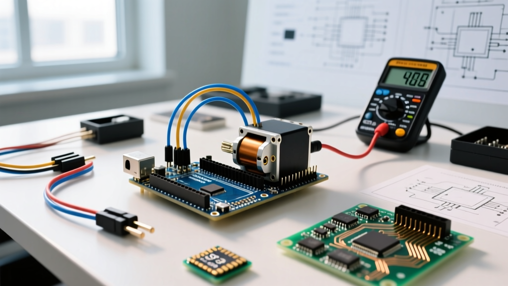
Power the driver's logic pin (VDD) with 5V from the Arduino. Connect your multimeter's positive probe to the Vref test point and the negative probe to the Arduino GND. Turn the brass potentiometer until you read exactly 0.68V.
Wiring & The Homing Switch Requirement
Open-loop stepper systems have no innate awareness of their physical position upon boot. To guarantee absolute accuracy for your 3 angles, you must establish a mechanical zero-point using a limit switch.
- STEP Pin: Arduino D3
- DIR Pin: Arduino D2
- Limit Switch: Connected to Arduino D9 (using INPUT_PULLUP)
- DRV8825 M0, M1, M2: All connected to 5V (Configures 1/16 microstepping)
For physical verification of your angles, mount a digital protractor (such as the Wixey WR300 Type 2, ~$35) directly to the motor shaft. This provides ground-truth data to compare against the theoretical firmware calculations.
The Arduino Code for Stepper Motor for 3 Different Angles
For precision movement, the native stepper.h library is insufficient because it lacks acceleration profiling. Sudden starts and stops cause rotor inertia to outpace the magnetic field, resulting in missed steps. We use Mike McCauley's AccelStepper Library, which implements trapezoidal acceleration ramps.
#include <AccelStepper.h>

// Define pins
const int stepPin = 3;
const int dirPin = 2;
const int homeSwitchPin = 9;

// Initialize AccelStepper (DRIVER mode uses step/dir pins)
AccelStepper stepper(AccelStepper::DRIVER, stepPin, dirPin);

// Define target angles and calculate steps (1/16 microstepping = 3200 steps/rev)
const float STEPS_PER_DEGREE = 3200.0 / 360.0; // 8.888 steps per degree
long angle1_steps = 45.0 * STEPS_PER_DEGREE;   // 400 steps
long angle2_steps = 90.0 * STEPS_PER_DEGREE;   // 800 steps
long angle3_steps = 135.0 * STEPS_PER_DEGREE;  // 1200 steps

void setup() {
  Serial.begin(115200);
  pinMode(homeSwitchPin, INPUT_PULLUP);

  // Set acceleration and max speed to prevent mid-band resonance stalls
  stepper.setMaxSpeed(800);      // 800 steps/sec = 1.5 rev/sec
  stepper.setAcceleration(1200); // Smooth ramp up

  // Home the motor to establish absolute zero
  homeStepper();
}

void loop() {
  // Move to Angle 1 (45 degrees)
  stepper.moveTo(angle1_steps);
  stepper.runToPosition();
  Serial.println("Reached 45 deg");
  delay(1500);

  // Move to Angle 2 (90 degrees)
  stepper.moveTo(angle2_steps);
  stepper.runToPosition();
  Serial.println("Reached 90 deg");
  delay(1500);

  // Move to Angle 3 (135 degrees)
  stepper.moveTo(angle3_steps);
  stepper.runToPosition();
  Serial.println("Reached 135 deg");
  delay(1500);

  // Return to absolute zero
  stepper.moveTo(0);
  stepper.runToPosition();
  Serial.println("Homed");
  delay(3000);
}

void homeStepper() {
  Serial.println("Homing...");
  // Spin backward slowly until the limit switch is triggered (LOW)
  while (digitalRead(homeSwitchPin) == HIGH) {
    stepper.moveTo(stepper.currentPosition() - 2);
    stepper.run();
  }
  // Reset internal position counter to absolute zero
  stepper.setCurrentPosition(0);
  Serial.println("Home established.");
}
Code Breakdown: Absolute vs. Relative Positioning
The most critical E-E-A-T distinction in this code is the use of stepper.moveTo() (absolute positioning) rather than stepper.move() (relative positioning).
If you use relative positioning and the motor misses a single microstep due to mechanical binding, every subsequent movement will be off by that exact amount. By commanding absolute coordinates (e.g., moveTo(800)), the AccelStepper library calculates the exact delta from its internal position register. If a step is missed, the library's internal math remains tied to the theoretical absolute coordinate, preventing catastrophic cumulative drift in automated sequences.
Real-World Calibration Workflow
Uploading the code is only 50% of the calibration process. Follow this workflow to verify accuracy:
- Secure the Mount: Ensure the motor is bolted to a heavy, rigid surface. Micro-vibrations can trigger the DRV8825's over-current protection.
- Attach the Protractor: Clamp the Wixey WR300 to the shaft. Zero it while the motor is at the homed limit switch position.
- Run the Sequence: Let the code cycle 10 times. Stepper motors exhibit slight thermal expansion in the rotor shaft as the coils heat up. The 10th cycle will yield the most accurate real-world operating data.
- Record Deviations: If the 90° command yields 89.8° on the protractor, you are experiencing mechanical backlash or belt stretch (if using a pulley system). You can compensate in firmware by adding a +2 step offset to your target variables.
Troubleshooting Missed Steps & Resonance
If your digital protractor shows the motor is consistently under-rotating (e.g., reaching 88° instead of 90°), you are likely hitting mid-band resonance. Stepper motors suffer from a severe torque dip between 150 and 300 RPM.
According to the SparkFun EasyDriver Hookup Guide and advanced tuning manuals, you can mitigate this by:
- Increasing Acceleration: Push through the resonant frequency band faster by raising
stepper.setAcceleration()from 1200 to 2500. - Adding Mechanical Inertia: Attaching a heavy coupling or flywheel to the shaft dampens the harmonic ringing that causes the rotor to stall.
- Checking Vref under load: Measure the Vref test point while the motor is actively holding torque. If the 5V logic rail from the Arduino sags under load, the DRV8825 current limit will drop proportionally, leading to stalls.
By combining rigorous mathematical step-calculation, physical Vref tuning, and absolute-position firmware architecture, you eliminate the guesswork from stepper motor integration, ensuring your 3 target angles are hit with sub-degree repeatability every single cycle.