
The Short Answer: Why Your FC-37 or YL-83 Sensor Feels Hot
When building a leak detection or automated plant watering system, a common and alarming observation leads many hobbyists to search: is the water sensor supposed to get hot arduino? The short answer is no, your sensor should not be hot, but it will naturally become warm if wired incorrectly. The ubiquitous FC-37 and YL-83 rain/water sensor modules (typically priced around $1.50 to $3.00) are notorious for heating up when left continuously powered via the Arduino's 5V VCC pin.
This heating is not a defect in the traditional sense, but rather a byproduct of poor circuit design combined with the electrochemical realities of passing direct current (DC) through exposed copper traces and water. To understand exactly why this happens—and how to prevent your sensor from destroying itself—we need to look past the basic tutorials and dive directly into the component datasheets and the physics of galvanic corrosion.
Datasheet Breakdown: The LM393 Comparator & Thermal Limits
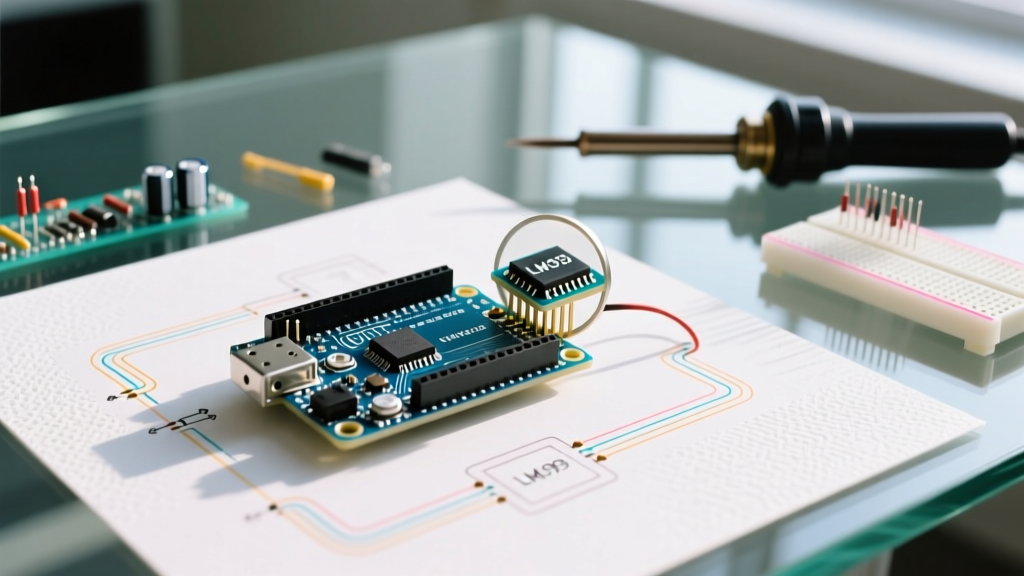
At the heart of almost every cheap Arduino water sensor module is the LM393 dual differential comparator. This IC is responsible for comparing the voltage drop across the exposed sensor traces against a reference voltage set by the onboard potentiometer, outputting a clean HIGH or LOW digital signal.
According to the Texas Instruments LM393 product specifications, the IC itself is highly efficient. The typical quiescent current (the current the chip draws just to stay on) is a mere 0.4 mA per comparator. At a 5V supply, the LM393 is only dissipating about 2 to 4 milliwatts of power. This is virtually imperceptible to the human touch and cannot account for the heat you are feeling.
Where is the Heat Actually Coming From?
The heat you feel on the sensor board is generated by the peripheral passive components and the sensor traces themselves. The module features a voltage divider network, a power indicator LED, and a status LED. When the sensor is submerged or exposed to heavy condensation, the resistance of the water bridging the exposed PCB traces drops significantly.
| Component / State | Typical Current Draw | Power Dissipation (at 5V) | Thermal Output |
|---|---|---|---|
| LM393 IC (Quiescent) | 0.8 mA | 4 mW | Negligible (Ambient) |
| Power LED + Resistor | 10 - 15 mA | 50 - 75 mW | Mildly Warm |
| Water Bridging Traces (Low Resistance) | 15 - 30 mA | 75 - 150 mW | Noticeably Hot |
When the sensor is wet, the total current draw can easily spike to 30 mA or more. While 150 mW sounds small, it is concentrated on a tiny PCB footprint with minimal copper area for heat sinking, causing the board temperature to rise to 40°C–45°C (104°F–113°F), which feels distinctly hot to the touch.
The Real Culprit: Electrolysis and Galvanic Corrosion
The heat is actually a secondary symptom of a much more destructive process. When you leave the sensor continuously powered, you are passing a steady DC current through the water bridging the nickel or copper traces. This triggers electrolysis.
⚠️ Datasheet & Chemistry Warning: Electrolysis causes the anode trace to rapidly oxidize and dissolve into the water. Even if the sensor only gets 'warm,' the continuous current will eat through the exposed metal traces in a matter of days, permanently destroying a $2 sensor. The heat is simply the electrical resistance of the degrading metal and the ionized water.
This is why industrial liquid level sensors do not use exposed, continuously powered DC traces. They either use alternating current (AC) to prevent ion buildup, or they pulse the DC current for mere milliseconds to take a reading before cutting the power entirely.
The "Always-On" Mistake: Arduino GPIO vs. VCC Wiring
Most beginner tutorials instruct you to wire the sensor's VCC pin directly to the Arduino's 5V or 3.3V output. This guarantees the sensor is always on, always drawing current, always generating heat, and always corroding. The solution is to treat the sensor as a peripheral that must be "woken up" only when a reading is required.
Wiring Comparison Matrix
| Wiring Method | Heat Generation | Corrosion Rate | Sensor Lifespan | Code Complexity |
|---|---|---|---|---|
| VCC to Arduino 5V Pin | High (Continuous) | Rapid (Days) | 1 - 2 Weeks | None (Always On) |
| VCC to Arduino Digital GPIO | Negligible (Pulsed) | Extremely Slow | 1 - 3 Years | Low (Requires pin toggling) |
| VCC via N-Channel MOSFET | None | None | 3+ Years | Medium (Requires extra hardware) |
Step-by-Step Fix: Pulsing Power to Eliminate Heat
Because the YL-83 and FC-37 modules draw a maximum of roughly 30 mA when wet, they fall safely within the current sourcing capabilities of the Arduino's microcontroller. According to the Microchip ATmega328P datasheet, the absolute maximum DC current per I/O pin is 40 mA, with a recommended operating limit of 20 mA. While 30 mA slightly exceeds the recommended continuous limit, it is perfectly safe for a pulsed duration of a few milliseconds.
Implementation Steps:
- Rewire the Module: Disconnect the sensor's VCC pin from the Arduino's 5V rail. Connect it instead to a digital GPIO pin (e.g., Digital Pin 8).
- Initialize the Pin: In your
setup()function, set Pin 8 as anOUTPUTand write itLOWto ensure the sensor starts in the powered-off state. - Pulse for Reading: When you need to check for water, write Pin 8
HIGH. - Stabilize and Read: Wait for 10 to 20 milliseconds. This allows the LM393 comparator's internal capacitors to charge and the analog voltage to stabilize.
- Execute analogRead(): Take your reading from the analog pin.
- Cut the Power: Immediately write Pin 8
LOW. This stops the current flow, eliminates the heat, and halts the electrolysis process.
By using this pulsing method, the sensor is only powered for roughly 20 milliseconds every few minutes. The average current draw drops to microamps, the board remains completely cool to the touch, and the lifespan of the exposed traces increases exponentially.
Upgrading to Industrial Alternatives
If your project requires long-term reliability, continuous monitoring, or deployment in harsh environments (like a greenhouse or basement sump pump), the $2 FC-37 sensor is the wrong tool for the job, regardless of how you wire it. The exposed traces will eventually degrade due to ambient humidity and oxidation.
For professional deployments, consider upgrading to industrial alternatives:
- Stainless Steel Liquid Level Sensors ($12.00 - $18.00): These use sealed, corrosion-resistant probes and often feature built-in optocouplers to isolate the high-current switching from your microcontroller.
- Capacitive Soil Moisture Sensors v1.2 ($4.00 - $6.00): Unlike resistive sensors, capacitive sensors measure the dielectric permittivity of the surrounding medium. They have no exposed metal traces that pass current through the water, entirely eliminating electrolysis and heat generation.
- Sensirion SHT3x Series ($8.00 - $15.00): For ambient leak detection based on localized humidity spikes, the Sensirion environmental sensors offer I2C digital outputs, extreme accuracy, and zero risk of water-induced short circuits.
Frequently Asked Questions (FAQ)
Can the heat from the water sensor damage my Arduino?
No. The heat is localized to the sensor's PCB and the water droplets. The sensor draws a maximum of 30-40 mA, which is well within the Arduino's onboard 5V voltage regulator's capacity (typically 500 mA to 1A). The Arduino board itself will not be damaged by the sensor's thermal output.
Why does my sensor read 'dry' when it's submerged, but gets burning hot?
If the sensor gets hot but reads dry (HIGH on digital, or near 1023 on analog), your potentiometer is likely tuned to a threshold higher than the voltage drop caused by the water. The current is still flowing (causing heat and electrolysis), but the LM393 comparator isn't triggering the digital flip. Recalibrate the blue potentiometer with a small Phillips screwdriver while the sensor is in the target water depth.
Is it safe to power the sensor directly from a 9V battery?
Absolutely not. The LM393 can handle up to 36V, but the peripheral LEDs and the voltage divider network on these cheap modules are rated strictly for 3.3V to 5V. Applying 9V will instantly burn out the power LED, potentially overheat the voltage divider resistors, and destroy the module.