
The Architectural Divide: How to Use PWM on Arduino Effectively
Pulse Width Modulation (PWM) is the backbone of microcontroller peripheral control, allowing digital pins to simulate analog outputs by rapidly toggling between HIGH and LOW states. When makers and engineers ask how to use PWM on Arduino, the answer usually defaults to the analogWrite() function. However, treating all PWM signals as identical is a critical mistake that leads to jittery servos, audible motor whine, and CPU bottlenecks.
In 2026, the ecosystem has expanded far beyond the classic 8-bit AVR boards. Understanding the difference between Hardware PWM (offloaded to dedicated silicon timers) and Software PWM (bit-banged via CPU interrupts) is essential for reliable sensor and peripheral integration. This guide compares these methods across the most popular boards and provides actionable wiring and tuning frameworks for real-world components.
Hardware vs. Software PWM: Component Comparison Matrix
Before wiring up a motor driver or LED array, you must choose the right PWM generation method. Hardware PWM relies on the microcontroller's internal timer/counters, freeing the CPU to handle I2C sensors or serial communication. Software PWM uses libraries to manually toggle pins via timed interrupts.
| Feature | Hardware PWM (e.g., analogWrite) | Software PWM (e.g., SoftwareServo) |
|---|---|---|
| CPU Overhead | Zero (handled by silicon timers) | High (requires constant CPU interrupts) |
| Signal Jitter | Negligible (perfect square waves) | High (susceptible to interrupt blocking) |
| Frequency Range | Fixed steps (490Hz to 62kHz+) | Highly flexible but unstable at high Hz |
| Pin Availability | Limited to specific timer-bound pins | Any digital GPIO pin |
| Best Use Case | DC motors, high-speed LED dimming | Extra hobby servos, low-frequency relays |
Board-by-Board PWM Capabilities & Specs
The implementation of analogWrite() varies wildly depending on the silicon. Here is how the three dominant architectures compare in the current market.
1. Arduino Uno R3 (ATmega328P) & R4 Minima
The classic Uno R3 (pricing around $27.50 for official boards, $12 for clones) utilizes the 8-bit ATmega328P microcontroller. It features three internal timers (Timer0, Timer1, Timer2) mapped to six specific PWM pins: 3, 5, 6, 9, 10, and 11.
- Resolution: 8-bit (0-255 duty cycle).
- Default Frequency: ~490 Hz for most pins, but ~980 Hz for pins 5 and 6.
- Critical Warning: Timer0 (pins 5 and 6) is hardwired to the
millis()anddelay()functions. If you alter Timer0's prescaler to change the PWM frequency, you will instantly break all time-based Arduino core functions.
2. Arduino Mega 2560
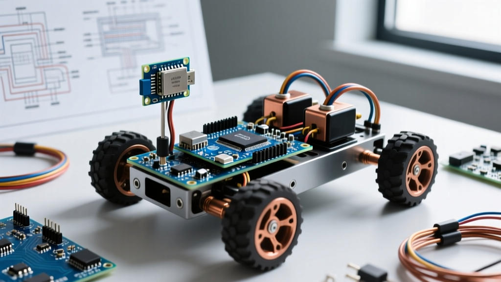
For complex robotics requiring multiple actuators, the Mega 2560 offers 15 hardware PWM pins (2-13 and 44-46). It utilizes 16-bit timers, allowing for much finer resolution and frequency control without sacrificing as many pins per timer. It remains the workhorse for 3D printers and CNC shields, though its 5V logic level requires level-shifters when interfacing with modern 3.3V sensors.
3. ESP32 (The Modern Standard)
The ESP32-DevKitC V4 (averaging $6.50) has largely replaced the Mega for advanced peripheral control. Instead of standard timers, the ESP32 uses a dedicated LEDC (LED Controller) peripheral. As of the Arduino ESP32 Core 3.x (standard in 2026), the traditional analogWrite() wrapper is finally stable, but for precise motor control, the native LEDC API is still superior.
- Channels: Up to 16 independent channels.
- Resolution: Up to 20-bit (0 to 1,048,575), allowing imperceptible LED fading.
- Logic Level: 3.3V. Never connect 3.3V ESP32 PWM pins directly to 5V logic motor drivers without a level shifter or optocoupler, or you risk back-feeding and frying the GPIO matrix.
Peripheral-Specific Tuning & Failure Modes
Knowing how to use PWM on Arduino is only half the battle; matching the PWM signal to the physical peripheral is where most projects fail. Below are the specific tuning parameters and edge cases for common components.
High-Power LEDs and LED Strips
When driving MOSFETs (like the IRLZ44N) to control 12V LED strips, the default 490Hz frequency is generally acceptable. However, if you are using PWM for high-speed camera lighting or optical sensors, 490Hz will cause severe banding and flicker.
Actionable Fix: Move the LED to Pin 9 or 10 (Timer1) on an Uno, and change the prescaler to achieve 31.25kHz. This pushes the flicker well beyond the threshold of human vision and high-speed camera shutters. Remember to use a 150Ω to 220Ω gate resistor to prevent high-frequency ringing on the MOSFET gate.
Hobby Servos (SG90, MG996R)
Servos do not use standard duty cycles; they require a very specific 50Hz signal (a 20ms period) where the HIGH pulse width dictates the angle (1ms to 2ms). The default analogWrite() outputs 490Hz, which will cause a servo to twitch violently, overheat, and draw excessive current, potentially triggering a brownout reset on your Arduino.
Actionable Fix: Always use the hardware Servo.h library for the first 12 servos, as it hijacks Timer1 to generate a perfect 50Hz hardware signal. If you must use Software PWM for extra servos on arbitrary pins, ensure your main loop does not contain blocking code like delay(), or the software interrupts will desync, causing severe mechanical jitter.
DC Motors via Motor Drivers
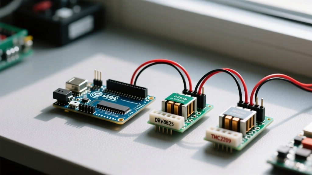
When driving DC motors, the choice of motor driver dictates how PWM behaves. The ancient L298N H-Bridge (costing ~$3.50) uses Bipolar Junction Transistors (BJTs). It suffers from a massive ~2V voltage drop and requires a high minimum PWM duty cycle (often >80 out of 255) just to overcome internal friction and voltage loss. At 490Hz, the L298N will also generate a loud, annoying audible whine.
Actionable Fix: Upgrade to a TB6612FNG or DRV8833 driver (approx. $4.50). These use MOSFETs, dropping only ~0.5V, allowing smooth low-speed PWM control down to a duty cycle of 20. To eliminate the 490Hz motor whine, use the Timer1 prescaler trick detailed below.
Advanced Trick: Silencing DC Motor Whine (31kHz PWM)
The audible whine from DC motors and ceramic capacitors on motor drivers is caused by the 490Hz PWM frequency vibrating the motor windings and piezoelectric components. By pushing the frequency into the ultrasonic range (>20kHz), the system becomes completely silent.
Pro-Tip: Only apply this to Timer1 (Pins 9 and 10 on the Uno). Altering Timer0 will destroy yourmillis()timing, and altering Timer2 will break thetone()function.
To change Pins 9 and 10 to 31.25kHz, place this single line of code at the very end of your setup() function:
TCCR1B = (TCCR1B & B11111000) | B00000001;
What this does: It masks the last three bits of the Timer1 Control Register B and sets the prescaler to 1 (no prescaling). With a 16MHz clock, the math results in exactly 31,250 Hz. Your analogWrite(9, 128) will now run silently and smoothly, vastly improving the acoustic profile of robotics and RC projects.
Summary: Choosing the Right Path
Mastering how to use PWM on Arduino requires looking past the basic analogWrite() documentation. For simple LED fading, default hardware PWM is sufficient. For servos, dedicated 50Hz hardware libraries are mandatory to prevent jitter. For high-performance DC motor control, migrating to MOSFET-based drivers like the TB6612FNG and utilizing ultrasonic 31kHz timer prescalers will yield professional-grade, silent operation. Always verify your logic levels—especially when integrating 3.3V ESP32 boards with 5V peripherals—to ensure long-term hardware reliability.