
Introduction to Photoresistors and the GL5528
Interfacing an LDR and Arduino is a foundational project for any electronics hobbyist or engineering student. A Light Dependent Resistor (LDR), also known as a photoresistor or Cadmium Sulfide (CdS) cell, is a passive analog component whose electrical resistance decreases as incident light intensity increases. According to the All About Circuits semiconductor textbook, the photoconductive effect in CdS cells occurs when photons excite electrons from the valence band to the conduction band, thereby increasing conductivity.
For this tutorial, we will use the GL5528 photoresistor, the most ubiquitous and cost-effective LDR on the market in 2026. It features a peak sensitivity wavelength of 540nm (green-yellow light, closely matching human eye sensitivity), a dark resistance of >1.0 MΩ, and an illuminated resistance of 10-20 kΩ at 10 Lux (typical twilight). When paired with an Arduino Uno R4 Minima or the classic Uno R3, it provides a reliable, low-cost solution for automated lighting, solar trackers, and security systems.
Component Checklist and 2026 Pricing
Before wiring the circuit, gather the following components. Prices reflect average 2026 hobbyist retail rates.
| Component | Model / Spec | Function | Est. Cost (USD) |
|---|---|---|---|
| Microcontroller | Arduino Uno R4 Minima | Processing & ADC | $27.50 |
| Photoresistor | GL5528 CdS Cell | Light Sensing | $0.05 (bulk) |
| Resistor | 10kΩ (1/4W, 1% tolerance) | Voltage Divider | $0.02 |
| Capacitor | 0.1µF Ceramic (104) | Hardware Noise Filter | $0.03 |
| Wiring | 22 AWG Solid Core | Breadboard Connections | $0.10 |
The Physics of the Voltage Divider: Why a 10kΩ Resistor?
Microcontrollers cannot measure resistance directly; they measure voltage. To convert the LDR's variable resistance into a readable voltage, we must build a voltage divider circuit. As detailed in the Electronics Tutorials voltage divider guide, the output voltage ($V_{out}$) is determined by the ratio of the two resistors in series.
The formula is: Vout = Vin * (R_fixed / (R_LDR + R_fixed))
Why choose exactly 10kΩ for $R_{fixed}$? The goal of a voltage divider in sensor interfacing is to maximize the voltage swing across your expected operating range. The GL5528 has a resistance of roughly 10kΩ to 20kΩ at dusk (10 Lux) and drops to about 1kΩ to 2kΩ in indoor lighting (100 Lux). By selecting a fixed resistor that sits near the geometric mean of your target resistance range ($\sqrt{1000 \times 100000} \approx 10,000\Omega$), you center the voltage swing around the mid-point of the Arduino's ADC range, ensuring maximum resolution where it matters most.
Step-by-Step Wiring Guide
Follow these exact steps to wire the LDR and Arduino. This configuration uses a pull-down resistor topology, meaning voltage increases as light increases.
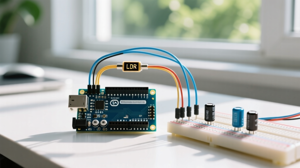
- Power the Breadboard: Connect the Arduino 5V pin to the positive (red) rail and the GND pin to the negative (blue) rail.
- Place the LDR: Insert the two legs of the GL5528 into separate rows on the breadboard. (LDRs are non-polarized, so orientation does not matter).
- Connect VCC: Run a jumper wire from the 5V rail to Leg 1 of the LDR.
- Place the 10kΩ Resistor: Insert one leg of the 10kΩ resistor into the same row as Leg 2 of the LDR. Insert the other leg into the GND rail.
- Analog Signal Tap: Connect a jumper wire from the junction of the LDR and the 10kΩ resistor to the Arduino's A0 analog input pin.
- Hardware Low-Pass Filter (Crucial): Insert the 0.1µF ceramic capacitor in parallel with the 10kΩ resistor (one leg in the A0 junction row, the other in the GND rail). This creates an RC low-pass filter that eliminates high-frequency electromagnetic interference (EMI) before it reaches the ADC.
Writing the Arduino Sketch: Beyond Basic analogRead
Beginners often rely on a single analogRead() call, which leaves the system vulnerable to transient noise. The Arduino analogRead() documentation notes that ADC readings can fluctuate by ±2 LSBs (Least Significant Bits) due to internal thermal noise and power supply ripple.
To achieve professional-grade stability, we implement a moving average software filter combined with hysteresis logic. Hysteresis prevents 'relay chatter'—a scenario where a connected light flickers rapidly on and off when ambient light hovers exactly at your threshold boundary.
// LDR and Arduino Interfacing with Moving Average & Hysteresis
const int ldrPin = A0;
const int relayPin = 8;

const int numReadings = 20; // Filter window size
int readings[numReadings];
int readIndex = 0;
long total = 0;
int averageLight = 0;

// Hysteresis thresholds (0-1023 scale for 10-bit ADC)
const int DARK_THRESHOLD = 400;  // Turn ON light when it gets dark
const int LIGHT_THRESHOLD = 550; // Turn OFF light when it gets bright

bool isLightOn = false;

void setup() {
  Serial.begin(115200);
  pinMode(relayPin, OUTPUT);
  digitalWrite(relayPin, LOW);

  // Initialize array
  for (int i = 0; i < numReadings; i++) {
    readings[i] = 0;
  }
}

void loop() {
  // Subtract the last reading
  total = total - readings[readIndex];

  // Read new value from A0
  readings[readIndex] = analogRead(ldrPin);

  // Add to total
  total = total + readings[readIndex];

  // Advance to next position
  readIndex = (readIndex + 1) % numReadings;

  // Calculate average
  averageLight = total / numReadings;

  // Hysteresis Logic
  if (averageLight < DARK_THRESHOLD && !isLightOn) {
    digitalWrite(relayPin, HIGH);
    isLightOn = true;
    Serial.println("State: DARK - Relay ON");
  }
  else if (averageLight > LIGHT_THRESHOLD && isLightOn) {
    digitalWrite(relayPin, LOW);
    isLightOn = false;
    Serial.println("State: BRIGHT - Relay OFF");
  }

  // Debug output
  Serial.print("Raw Avg: ");
  Serial.println(averageLight);
  delay(50); // 50ms polling rate
}
Advanced Troubleshooting: Edge Cases and Failure Modes
When deploying an LDR and Arduino circuit in real-world environments, you will encounter specific physical and electrical edge cases.
Edge Case 1: Non-Linear Response and ADC Resolution
The GL5528's resistance-to-lux curve is logarithmic, not linear. This means the voltage output will change rapidly in low-light conditions but flatten out in direct sunlight. If you are using a 3.3V microcontroller (like the ESP32 or Arduino Due) with a 12-bit ADC (0-4095 range), you must scale your thresholds accordingly. Furthermore, ensure your Arduino's reference voltage is stable; if powering via USB, VCC can fluctuate between 4.7V and 5.2V, shifting your analog readings. For precision applications, use the analogReference(INTERNAL) function to lock the ADC reference to a stable internal bandgap voltage (1.1V on Uno R3), though this requires scaling down your voltage divider output to stay under 1.1V.
Edge Case 2: Thermal Drift and Physical Placement
CdS photoresistors are sensitive to temperature. The epoxy coating on the GL5528 can act as a minor thermal insulator. If you place the LDR too close to a heat-generating component—such as an LM7805 linear voltage regulator or a power relay coil—the localized heat will alter the sensor's baseline resistance, causing false triggers. Always mount the LDR at least 2 inches away from heat sinks and power components, ideally protruding through an enclosure's front panel.
Edge Case 3: Slow Response Time
Unlike digital photodiodes, LDRs have a relatively slow rise and fall time, typically between 20ms and 50ms. While this is perfectly adequate for dusk-to-dawn lighting controllers, an LDR and Arduino setup is entirely unsuited for high-speed optical encoders, barcode scanning, or pulse-width modulation (PWM) light communication. If your project requires detecting light fluctuations faster than 10Hz, you must upgrade to a digital sensor.
Component Comparison: LDR vs. Modern Digital Sensors
While the GL5528 is an excellent learning tool and cost-effective for basic automation, modern digital light sensors offer superior precision. Below is a comparison matrix to help you decide if an LDR is the right choice for your specific 2026 project.
| Feature | GL5528 (Analog LDR) | BH1750 (Digital I2C) | TSL2591 (High Dynamic Range) |
|---|---|---|---|
| Interface | Analog (Voltage Divider) | I2C Digital | I2C Digital |
| Output Metric | Relative Voltage (0-1023) | Calibrated Lux (1 - 65535) | Calibrated Lux (up to 88,000) |
| IR/UV Rejection | Poor (Broad spectrum) | Good (Visible focus) | Excellent (Separate IR/Vis diodes) |
| Response Time | ~20-50ms | ~120ms (Integration dependent) | ~100ms |
| Approx. Cost | $0.05 | $1.50 | $4.50 |
| Best Use Case | Simple dusk/dawn triggers | Display backlight dimming | Outdoor weather stations |
Summary
Mastering the interfacing of an LDR and Arduino requires moving beyond simple resistance measurements. By understanding the logarithmic nature of CdS cells, implementing a mathematically optimized 10kΩ voltage divider, and utilizing both hardware RC filtering and software hysteresis, you can build a light-sensing system that is immune to EMI and relay chatter. Whether you are building an automated greenhouse shading system or a smart streetlamp prototype, these foundational analog interfacing techniques remain essential skills in the modern maker's toolkit.