
The Fatal Flaw in Default Arduino Ultrasonic Sensor Code
When most makers and engineers begin prototyping distance measurement, they rely on the standard pulseIn() function. While this approach is ubiquitous in beginner tutorials, deploying standard Arduino ultrasonic sensor code built on pulseIn() in a production environment, a multi-sensor rover, or an industrial tank monitor is a recipe for system failure.
The core issue is architectural: pulseIn() is a strictly blocking function. When you call pulseIn(echoPin, HIGH, 30000), the microcontroller halts all other operations and waits for the echo pin to go HIGH, then LOW, or until the 30-millisecond timeout expires. If you are polling four HC-SR04 sensors sequentially and they all fail to return an echo (a common occurrence with soft or angled targets), your main loop just hung for 120 milliseconds. In a 50Hz PID control loop for a balancing robot or autonomous rover, a 120ms dead zone guarantees catastrophic oscillation and system crashes.
To build robust, responsive embedded systems, we must abandon blocking delays and adopt interrupt-driven, non-blocking driver architectures. According to the official Arduino pulseIn() Reference, the function simply counts clock cycles, offering zero hardware-level optimization for background processing.
Enter NewPing: The Industry-Standard Driver Library
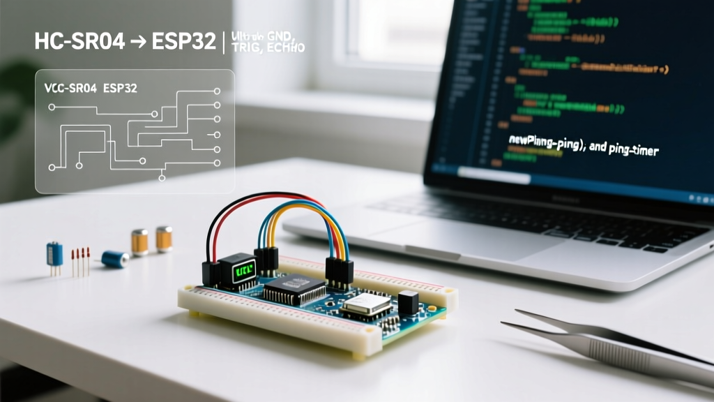
Tim Eckel’s NewPing Library Documentation remains the gold standard for ultrasonic interfacing in 2026. Instead of relying on software delay loops, NewPing leverages hardware timers (specifically Timer2 on 8-bit AVR microcontrollers like the ATmega328P) to trigger pings and read echoes via interrupts.
Blocking vs. Non-Blocking Architecture
| Feature | Standard pulseIn() | NewPing (Timer Interrupts) |
|---|---|---|
| Execution Type | Blocking (Halts CPU) | Non-Blocking (Background ISR) |
| Max Distance Limit | Manual timeout calc required | Hardcoded limit prevents hang |
| Multi-Sensor Support | Poor (Sequential hanging) | Excellent (Event-driven polling) |
| Median Filtering | Manual array implementation | Built-in ping_median() |
| CPU Overhead | High (Active waiting) | Negligible (Hardware Timer) |
By capping the maximum distance parameter (e.g., 200cm), NewPing calculates the exact microsecond timeout required. If an echo is missed, the interrupt service routine (ISR) flags a zero return instantly, freeing the CPU to handle motor control, telemetry, or display rendering.
Hardware Matrix: Selecting the Right Transceiver for 2026
Your code is only as reliable as the physics of your hardware. The market has evolved past the generic, unbranded HC-SR04. Here is a breakdown of the current ultrasonic ecosystem and their specific driver requirements.
| Sensor Model | Avg. Price (2026) | Logic Level | Interface | Best Use Case |
|---|---|---|---|---|
| HC-SR04 | $2.00 - $3.50 | 5V Only | Analog Pulse | Basic 5V Arduino Uno prototypes |
| HC-SR04P | $3.00 - $4.50 | 3.3V - 5V | Analog Pulse | ESP32, RP2040, STM32 integration |
| JSN-SR04T | $14.00 - $18.00 | 5V Only | Analog Pulse | Outdoor, waterproof, liquid level |
| US-100 | $6.00 - $9.00 | 3.3V - 5V | UART / Pulse | Noisy environments (UART bypasses analog timing) |
Critical Warning: Connecting a standard 5V HC-SR04 Echo pin directly to a 3.3V GPIO on an ESP32 or Raspberry Pi Pico will eventually fry the microcontroller's input buffer. Always use the 'P' variant (HC-SR04P) for 3.3V logic, or implement a bidirectional logic level shifter (like the Texas Instruments TXS0102E) which costs roughly $1.50 on a breakout board.
Implementing Non-Blocking Arduino Ultrasonic Sensor Code
Below is the structural implementation of a non-blocking ping using NewPing. This setup allows your loop() to run at thousands of iterations per second while the sensor operates silently in the background.
#include <NewPing.h>

#define TRIGGER_PIN  12
#define ECHO_PIN     11
#define MAX_DISTANCE 200 // Max distance in cm (limits timeout)
#define PING_INTERVAL 35 // Milliseconds between pings

NewPing sonar(TRIGGER_PIN, ECHO_PIN, MAX_DISTANCE);

unsigned long pingTimer;
unsigned int currentDistance = 0;

void setup() {
  Serial.begin(115200);
  pingTimer = millis();
}

void loop() {
  // Non-blocking timer check
  if (millis() >= pingTimer) {
    pingTimer += PING_INTERVAL;
    // Trigger ping via Timer2 interrupt
    sonar.ping_timer(echoCheck);
  }

  // CPU is free here to run motors, read IMUs, etc.
  runMotorControl();
}

// Interrupt Service Routine (ISR)
void echoCheck() {
  if (sonar.check_timer()) {
    // Ping successful, convert raw time to cm
    currentDistance = sonar.ping_result / US_ROUNDTRIP_CM;
  } else {
    currentDistance = 0; // Out of range or missed echo
  }
}
Expert Insight: The US_ROUNDTRIP_CM constant in NewPing is hardcoded to 29. This represents the number of microseconds it takes for sound to travel 1 cm out and 1 cm back at roughly 20°C. As we will see in the next section, this static assumption is a major source of error in variable-temperature environments.Advanced Physics: Temperature Compensation
The speed of sound in dry air is not a static 343 meters per second. It fluctuates based on ambient temperature. According to data from the Engineering Toolbox: Speed of Sound in Air, the velocity of sound shifts by approximately 0.6 m/s for every 1°C change.
If you are using an ultrasonic sensor to measure the volume of a 4-meter-tall outdoor agricultural silo, a temperature swing from 5°C in the morning to 35°C in the afternoon will alter the speed of sound from ~334 m/s to ~352 m/s. This introduces a measurement error of over 20 centimeters—enough to trigger false overflow alarms.
Dynamic Compensation Algorithm
To fix this, integrate a DS18B20 waterproof temperature probe and dynamically adjust your conversion divisor in the code:
float getTempCompensatedDistance(unsigned int pingTimeUs, float tempC) {
  // Calculate speed of sound in cm/us based on temperature
  float speedOfSound = (331.4 + (0.606 * tempC)) / 10000.0;

  // Distance = (Time * Speed) / 2
  float distanceCm = (pingTimeUs * speedOfSound) / 2.0;
  return distanceCm;
}
By replacing the static division with this physics-based calculation, your Arduino ultrasonic sensor code transitions from a hobbyist script to an industrial-grade measurement tool.
Troubleshooting Edge Cases and Hardware Failures
Even with perfect code, ultrasonic transceivers are subject to acoustic physics and electrical noise. Here is how to diagnose and resolve the most common field failures.
1. Acoustic Cross-Talk in Multi-Sensor Arrays
If you mount four HC-SR04 sensors on a rover chassis and fire them simultaneously, Sensor A will detect the echo from Sensor B's acoustic burst, resulting in phantom 'obstacle detected' readings. Solution: Never fire sensors concurrently. Implement a sequential firing queue with a minimum 35ms delay between pings to allow acoustic dissipation. NewPing's multi-sensor event array handles this natively.
2. The 'Zero' Read vs. The 'Max' Read
A common bug in basic code is treating a '0' return as 'zero centimeters away'. In reality, ultrasonic sensors have a blind spot (usually 2cm to 20cm, depending on the model). If an object is inside the blind spot, the echo returns before the transceiver finishes ringing, and the controller registers a 0. Solution: Program your logic to treat distance == 0 as 'Out of Range / Error', not 'Collision Imminent'.
3. Power Supply Sag and Phantom Resets
The HC-SR04 draws a spike of roughly 15mA to 30mA during the 40kHz burst transmission. If you are powering three sensors directly from the Arduino Uno's 5V linear regulator, the voltage will sag, causing the ATmega328P to brownout and reset. Solution: Power ultrasonic arrays directly from a dedicated 5V buck converter (like an LM2596 module, ~$1.50) and tie the grounds together, bypassing the MCU's onboard regulator entirely.
Summary
Writing reliable Arduino ultrasonic sensor code requires moving past blocking functions and static assumptions. By leveraging the NewPing library for non-blocking hardware interrupts, selecting the correct logic-level hardware for your microcontroller, and applying environmental temperature compensation, you eliminate the timing hangs and physical inaccuracies that plague standard implementations. Whether you are building a 2026 autonomous delivery rover or a municipal water level telemetry node, these driver-level optimizations are mandatory for field reliability.