
The Myth of 'Factory Calibrated' Arduino Sensors
When building a temperature sensor Arduino project, it is tempting to trust the out-of-the-box readings from popular components like the DS18B20, TMP36, or LM35. Datasheets often boast 'factory calibrated' specifications, but these are statistical guarantees tested in multi-million-dollar semiconductor fabs under ideal conditions. In the real world of DIY electronics, breadboard parasitic capacitance, voltage regulator ripple, and cheap copper wiring introduce immediate offsets. If you are logging environmental data, managing a DIY reflow oven, or monitoring a hydroponic nutrient reservoir, an uncalibrated sensor can drift by 1.5°C to 3°C, rendering your automation logic useless.
This guide bypasses generic tutorials and provides a rigorous, metrology-inspired approach to calibrating analog and digital temperature sensors using accessible materials. We will cover two-point linear regression, hardware noise mitigation, and the hidden accuracy killers that ruin otherwise perfect code.
Sensor Accuracy Matrix: What You Are Actually Working With
Before touching a single wire, you must understand the inherent limitations of your chosen hardware. As of 2026, the market is saturated with both genuine silicon and cloned alternatives. Here is how the most common sensors stack up regarding baseline accuracy and calibration necessity.
| Sensor Model | Type | Datasheet Accuracy | Real-World Drift | Typical Cost (2026) | Calibration Method |
|---|---|---|---|---|---|
| Analog Devices DS18B20 (Genuine) | Digital (1-Wire) | ±0.5°C (-10 to +85°C) | ±0.2°C offset | $4.50 - $6.00 | Single-point offset |
| Cloned DS18B20 (Amazon/AliExpress) | Digital (1-Wire) | Unknown | Up to ±4.0°C | $1.00 - $1.50 | Two-point linear regression |
| Texas Instruments TMP36 | Analog (Voltage) | ±1.0°C (25°C) | ±1.5°C + Noise | $2.20 | Two-point + RC Filtering |
| Texas Instruments LM35 | Analog (Voltage) | ±0.5°C (25°C) | ±0.8°C + Noise | $3.50 | Single-point offset |
| Bosch BME280 | Digital (I2C/SPI) | ±1.0°C (0 to +65°C) | ±0.5°C + Self-heating | $5.00 - $8.00 | Single-point offset |
The Ice-Bath Method: Anchoring the 0°C Baseline
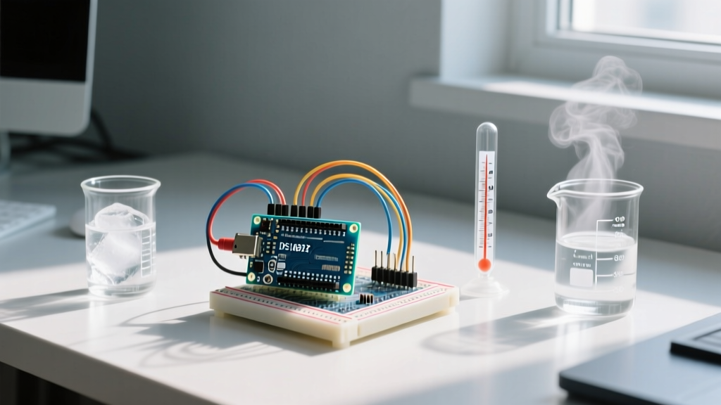
The most accessible and scientifically sound way to establish a baseline calibration point is the ice-bath method. However, simply dropping a sensor into a glass of ice water is a recipe for inaccurate data. You must create a proper slurry to ensure uniform thermal distribution.
Step-by-Step Ice-Bath Protocol
- Prepare the Slurry: Use crushed ice, not cubes. Cubes create air pockets that insulate the sensor. Fill an insulated thermos (to prevent ambient heat transfer) with 70% crushed ice and 30% distilled water. Tap water contains dissolved minerals that slightly depress the freezing point.
- Stir and Equilibrate: Stir the mixture vigorously for two minutes. The goal is a thick slush. Let it sit for 10 minutes to reach true thermal equilibrium.
- Waterproof the Sensor: If using a bare TMP36 or LM35, seal it in a thin-walled heat-shrink tube with a dab of thermal paste inside, or use a factory-sealed DS18B20 waterproof probe. Never submerge bare analog ICs.
- Positioning: Suspend the probe in the center of the slurry. Do not let it touch the bottom or sides of the thermos, as the container's temperature will differ from the 0.0°C slurry.
- Record the Raw Data: Let the Arduino log the reading for 5 minutes. Discard the first 2 minutes as the probe's thermal mass adjusts. Average the remaining 3 minutes to find your
Raw_Zerovalue.
Expert Tip: If you are using a cloned DS18B20, you may notice the reading jumping erratically in the ice bath. Counterfeit chips often lack the internal bandgap reference precision of the genuine Analog Devices silicon. If your variance exceeds 0.2°C in a stable ice bath, discard the sensor; software averaging cannot fix fundamental silicon flaws.
Boiling Point Calibration & The Altitude Trap
To perform a two-point calibration (which corrects for both offset and slope/gain errors), you need a second reference point. Boiling water is the standard choice, but water does not always boil at 100°C. The boiling point drops as atmospheric pressure decreases with altitude. If you live in Denver, Colorado (1,600 meters above sea level), water boils at roughly 94.6°C. If you calibrate your Arduino assuming 100°C, your high-end readings will be permanently skewed.
Calculating Your True Boiling Point
Before boiling water, check your local barometric pressure and altitude. A reliable approximation formula for the boiling point of water based on altitude is:
Boiling_Point_C = 100 - (Altitude_in_Meters * 0.0033)
For ultimate precision, consult local meteorological data. Once you have your true boiling point, suspend your waterproof sensor in the steam just above the rolling boil (or in the boiling water if properly sealed), ensuring it does not touch the heated metal of the pot. Record the stabilized Raw_Boil value.
Applying Linear Regression in Arduino C++
With your Raw_Zero (at 0°C) and Raw_Boil (at your calculated boiling point) recorded, you can map the sensor's arbitrary output to true Celsius using linear interpolation. This is especially critical for analog sensors like the Texas Instruments LM35 or TMP36, where the Arduino's 10-bit ADC (Analog-to-Digital Converter) and 5V reference voltage introduce scaling errors.
Here is the mathematical implementation for your Arduino sketch:
// Calibration Constants derived from physical testing
const float RAW_ZERO = 52.0;   // ADC value or raw digital reading at 0°C
const float RAW_BOIL = 948.0;  // ADC value or raw digital reading at 94.6°C
const float TRUE_ZERO = 0.0;
const float TRUE_BOIL = 94.6;  // Adjusted for Denver, CO altitude

float getCalibratedTemp(float rawReading) {
  // Calculate the slope (gain)
  float slope = (TRUE_BOIL - TRUE_ZERO) / (RAW_BOIL - RAW_ZERO);

  // Apply linear equation: y = mx + b
  float calibratedTemp = (slope * (rawReading - RAW_ZERO)) + TRUE_ZERO;

  return calibratedTemp;
}
By embedding these constants in your code, you effectively eliminate the manufacturing tolerances of the sensor and the voltage reference drift of the Arduino's microcontroller.
Hidden Accuracy Killers: Hardware Edge Cases
Even with perfect mathematical calibration, physical environment factors will destroy your accuracy if ignored. According to guidelines on thermometry and sensor deployment from the National Institute of Standards and Technology (NIST), environmental coupling and electrical noise are the primary culprits in measurement drift.
- Analog Self-Heating: Sensors like the TMP36 and LM35 draw a small amount of quiescent current (typically 50µA to 150µA). In stagnant air, this current heats the sensor's epoxy casing, causing a false high reading of up to 0.5°C. Fix: Mount the sensor on a small PCB with thermal vias to act as a heat sink, or pulse the power via a MOSFET, reading the sensor only when active.
- ADC Voltage Reference Drift: If you are powering your Arduino via the USB port, the 5V line is regulated by a cheap onboard linear regulator that fluctuates with PC USB load. A 4.8V supply instead of 5.0V will skew a TMP36 reading by over 2°C. Fix: Never use
analogRead()with the default 5V reference for precision work. Connect a precision 4.096V reference IC to the AREF pin and useanalogReference(EXTERNAL)in your setup. - 1-Wire Parasitic Power Issues: The DS18B20 supports 'parasitic power' mode (drawing power from the data line). In this mode, the internal charge pump struggles during the high-current temperature conversion phase, leading to voltage droop and corrupted CRC data. Fix: Always use VDD (external power) mode for calibration and precision logging. Connect a 4.7kΩ pull-up resistor to the true 3.3V or 5V rail, not a microcontroller GPIO pin.
- Electromagnetic Interference (EMI): If your Arduino is switching relays or driving stepper motors, the resulting back-EMF will inject high-frequency noise into analog sensor lines. Fix: Use twisted-pair cabling (22 AWG) for all sensor runs. For analog sensors, solder a 10kΩ resistor in series with the signal line and a 0.1µF ceramic capacitor to ground at the Arduino pin, creating a hardware low-pass RC filter.
Frequently Asked Questions
How often should I recalibrate my Arduino temperature sensors?
For standard silicon sensors (DS18B20, LM35) operating within normal indoor environmental ranges (0°C to 50°C), a one-time calibration is usually sufficient for years. However, if the sensor is exposed to thermal shock (e.g., repeatedly moving from -20°C freezers to +80°C ovens), the epoxy packaging can develop micro-fractures, altering the thermal transfer characteristics. Recalibrate annually in high-stress environments.
Can I use the internal 1.1V Arduino reference for the TMP36?
Yes, and you should. The internal 1.1V bandgap reference of the ATmega328P is vastly more stable over temperature and time than the USB-derived 5V rail. Since the TMP36 outputs a maximum of ~1.5V (at 100°C), you must use a voltage divider or accept the limited range if using the 1.1V reference. Alternatively, use an external precision voltage reference for the best possible ADC resolution.
Why does my DS18B20 read 85°C on startup?
The value 85°C is the default power-on-reset value stored in the DS18B20's scratchpad memory. If your Arduino reads the sensor before the initial conversion is complete (which takes up to 750ms at 12-bit resolution), it will pull this default value. Ensure your code enforces a strict delay or uses the DallasTemperature library's setWaitForConversion(true) parameter during initialization.