
Introduction to Acoustic Mapping
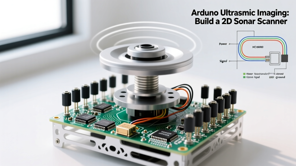
When most beginners think of the HC-SR04 ultrasonic sensor, they imagine a simple digital tape measure for robot obstacle avoidance. However, by combining a 40kHz ultrasonic transducer with a precision servo motor and a microcontroller, you can unlock the fundamentals of Arduino ultrasonic imaging. This technique, essentially a rudimentary form of sonar or acoustic radar, allows you to map the spatial geometry of a room, detect hidden objects, and generate 2D topographical heatmaps of your environment.
In this beginner interfacing tutorial, we will move beyond simple ping() distance readings. We will build a motorized 180-degree sweeping scanner, capture polar coordinate data, and translate those acoustic reflections into a visual 2D sonar map. Whether you are building an autonomous rover or exploring non-destructive testing (NDT) concepts, understanding acoustic beam profiles and multipath reflections is critical for modern embedded systems.
Bill of Materials (2026 Component Pricing)
To achieve reliable continuous sweeping without mechanical binding, we are bypassing the standard plastic-gear SG90 servo often found in starter kits. Metal gears are mandatory for the repetitive torque required in imaging applications.
| Component | Model / Specification | Estimated Cost (2026) | Role in Imaging System |
|---|---|---|---|
| Microcontroller | Arduino Uno R3 (ATmega328P) | $24.00 | Timing control and serial data streaming |
| Ultrasonic Sensor | HC-SR04 (40kHz Transducer) | $2.50 | Acoustic pulse emission and echo reception |
| Actuator | TowerPro MG90S (Metal Gear) | $6.50 | Precision angular positioning (0.1° resolution) |
| Power Supply | 5V 2A USB-C Buck Converter | $4.00 | Isolates servo current spikes from MCU logic |
| Hardware | M3 Nylon Standoffs & Hot Glue | $3.00 | Acoustic decoupling and rigid mounting |
Precision Wiring Matrix
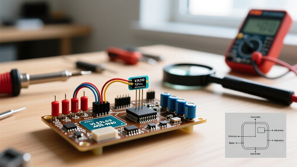
Acoustic imaging requires strict timing. A loose jumper wire causing a 5-microsecond delay will result in an 8.5mm spatial distortion in your final image. Use the following wiring matrix, ensuring your servo and sensor do not share the same 5V rail as the Arduino's onboard logic to prevent brownout resets during motor stalls.
| Component Pin | Arduino Uno R3 Pin | Notes & Edge Cases |
|---|---|---|
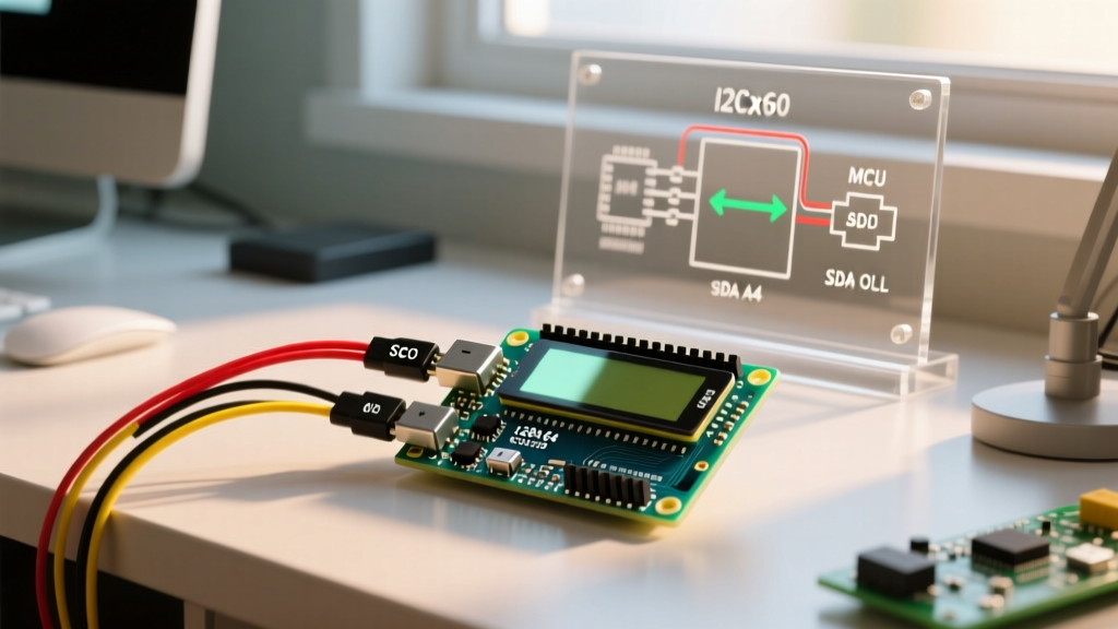
| HC-SR04 VCC | 5V (External Supply) | Do not use USB 5V; transducer draw spikes to 30mA. |
| HC-SR04 Trig | Digital Pin 9 | Set as OUTPUT. Requires 10µs HIGH pulse. |
| HC-SR04 Echo | Digital Pin 10 | Set as INPUT. Warning: Outputs 5V. Use a voltage divider if migrating to 3.3V ESP32 boards. |
| MG90S Signal | Digital Pin 11 | PWM control. 50Hz frequency (20ms period). |
| Shared GND | GND | Crucial: External supply GND and Arduino GND must be tied together. |
The Physics: Beam Angles and Temperature Drift
To interpret Arduino ultrasonic imaging data accurately, you must understand the physical limitations of the 40kHz piezoelectric transducers used in the HC-SR04. Unlike a laser LiDAR which operates with a beam divergence of less than 0.1 degrees, an ultrasonic sensor emits a conical sound wave with a 15-degree to 30-degree beam angle.
The Resolution Problem
Because of this wide acoustic cone, the sensor cannot distinguish between two objects placed side-by-side within that 15-degree field of view. It will only return the distance to the closest object that intersects the cone. Furthermore, the HC-SR04 has a physical blind spot of 2 centimeters. Any object closer than 2cm will cause the echo pulse to overlap with the trigger pulse, resulting in erratic timeout errors or false maximum-distance readings.
Temperature Compensation
Most beginner tutorials hardcode the speed of sound at 343 meters per second. However, acoustic velocity is highly dependent on ambient air temperature. According to principles outlined in Texas Instruments' ultrasonic sensing application notes, the speed of sound shifts by approximately 0.6 m/s for every 1°C change. If your scanner operates in an unheated garage at 5°C versus a living room at 22°C, your imaging scale will distort by nearly 3%. For precise imaging, integrate a DS18B20 temperature probe and apply the formula: v = 331.3 + (0.606 * Temperature_C).
Step-by-Step Assembly and Firmware Logic
- Mechanical Coupling: Mount the HC-SR04 to the MG90S servo horn using M3 nylon standoffs. Do not use hot glue directly on the transducer mesh; the acoustic impedance mismatch will dampen the 40kHz resonance and reduce your maximum range from 400cm to under 150cm.
- Counterweighting: The HC-SR04 weighs approximately 9 grams. Attach a small steel nut to the opposite side of the servo horn to balance the rotational inertia, preventing servo jitter at the 0° and 180° endpoints.
- Firmware Timing: In your Arduino IDE, utilize the Arduino Language Reference for the
pulseIn()function. Set a timeout of 25,000 microseconds. This caps the maximum readable distance at roughly 4.2 meters, preventing the MCU from hanging indefinitely if an echo is absorbed by soft furnishings. - Angular Stepping: Move the servo in 2-degree increments. A 1-degree step takes too long and introduces acoustic crosstalk (where the echo from the previous angle bleeds into the current reading). Allow a 40ms delay between steps to let residual acoustic energy dissipate.
Visualizing the Sonar Data
The Arduino itself cannot render graphics. To achieve true ultrasonic imaging, the MCU must act as a data acquisition (DAQ) node, streaming polar coordinates via Serial at 115200 baud. The data format should be structured as CSV: angle,distance.
On your host machine, use Processing or Python (with Matplotlib/Pygame) to read the serial stream. The host software must perform a polar-to-Cartesian conversion using basic trigonometry:
X = distance * cos(radians(angle))Y = distance * sin(radians(angle))
By plotting these X,Y coordinates and drawing a fading arc trail, you create a real-time 2D radar display. Objects like wooden chairs and metal trash cans will appear as solid bright lines, while angled walls will reflect sound away from the receiver, appearing as 'ghost' voids in your image.
Troubleshooting Common Imaging Artifacts
When your generated sonar map looks distorted or noisy, diagnose the issue using these specific failure modes:
- Multipath Reflections (Ghosting): If you see objects floating in empty space, the 40kHz pulse is likely bouncing off a nearby wall, hitting the target, and returning via a secondary bounce. This increases the time-of-flight, making the object appear further away and at the wrong angle.
- Acoustic Absorption (Dropouts): Materials with high acoustic impedance mismatches or porous structures—such as memory foam, heavy winter coats, or fiberglass insulation—will absorb the 40kHz wave entirely. The sensor will report a 400cm timeout, rendering the object 'invisible' to your scanner.
- Servo Jitter (Smearing): If the USB power supply cannot deliver the 800mA peak current required when the MG90S servo reverses direction at 180°, the voltage drop will cause the ATmega328P to briefly reset or the
pulseIn()timer to skew, resulting in a smeared, chaotic image on the right side of your display.
Beyond the HC-SR04: Phased Array Upgrades
While the HC-SR04 is the undisputed king of budget prototyping, serious industrial ultrasonic imaging in 2026 relies on solid-state phased arrays. Sensors like the MaxBotix MB7389 ($120+) offer narrow, software-configurable beam widths and RS232 digital outputs that eliminate the analog timing jitter inherent in the pulseIn() method. For those looking to transition from 2D sweeping to true 3D volumetric mapping without moving parts, exploring Murata's automotive-grade ultrasonic parking sensor arrays provides the next logical step in acoustic embedded systems engineering.