
The Hidden Bottlenecks of Arduino to Servo Integration
Connecting an arduino to servo motors is a foundational skill in embedded electronics, often taught using a simple SG90 micro-servo and a single digital pin. However, when you scale up to a multi-peripheral setup—integrating OLED displays, ultrasonic sensors, and high-torque servos simultaneously—the standard tutorial approach collapses. Direct wiring introduces severe hardware timer conflicts, I2C bus congestion, and catastrophic power rail brownouts. As of 2026, with hobbyists increasingly building complex robotic arms and automated camera gimbals, understanding the electrical and architectural nuances of multi-node peripheral integration is no longer optional; it is a requirement for system stability.
Timer Conflicts: Why Direct Wiring Fails in Multi-Sensor Nodes
The standard Arduino Servo Library relies on hardware timers to generate the precise 50 Hz PWM signal (a pulse every 20ms, with a high-time between 1ms and 2ms) required by hobby servos. On the ubiquitous ATmega328P (Arduino Uno/Nano), the Servo library defaults to commandeering Timer1.
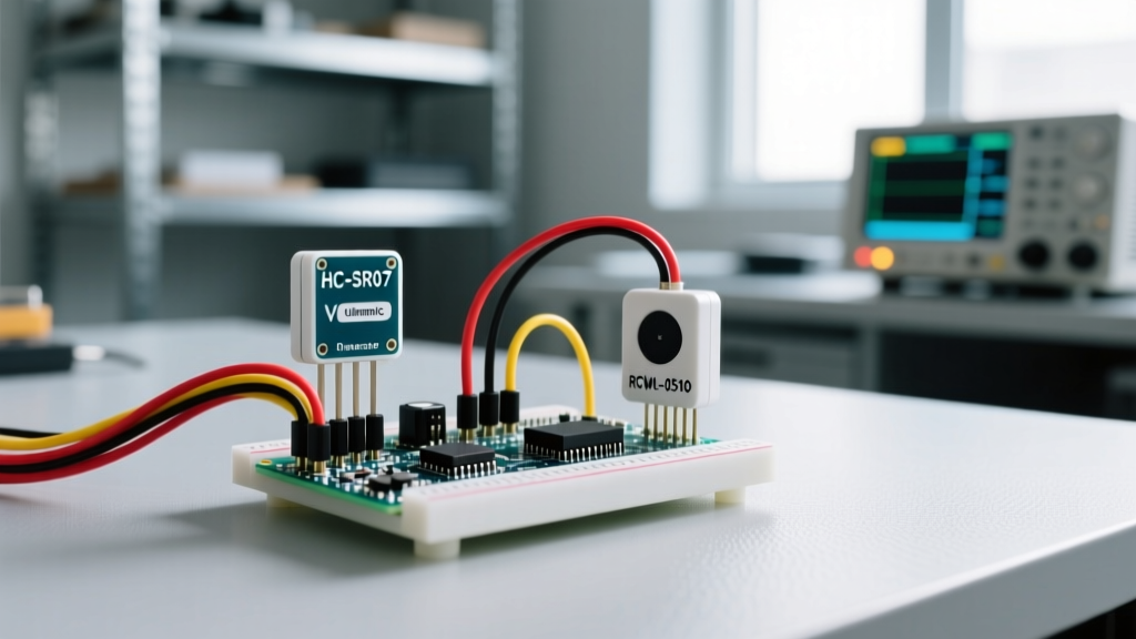
This creates a silent, often maddening conflict when you introduce other peripherals. If your multi-peripheral setup includes an HC-SR04 ultrasonic sensor using the pulseIn() function, or if you are using the analogWrite() function on pins 9 or 10 for LED dimming, your system will fail. Timer1 controls the PWM output on pins 9 and 10, and disabling it breaks those functions. Furthermore, heavy reliance on the microcontroller's internal timers for servo pulse generation consumes valuable CPU cycles, introducing jitter when the MCU is busy polling I2C sensors.
ATmega328P Timer and Pin Conflict Matrix
| Hardware Timer | Controlled Pins | Common Peripheral Conflicts | Servo Library Impact |
|---|---|---|---|
| Timer0 | Pins 5, 6 | delay(), millis(), Fast PWM motor control |
Not used by default Servo.h |
| Timer1 | Pins 9, 10 | analogWrite() (9/10), Ultrasonic pulseIn() blocking |
Hijacked by Servo.h (disables PWM on 9/10) |
| Timer2 | Pins 3, 11 | Tone generation, IRremote libraries | Used only if >12 servos are attached |
Power Architecture: Sizing for MG996R Stall Currents
The most common point of failure in an arduino to servo multi-peripheral setup is power delivery. A standard TowerPro MG996R metal-gear servo draws roughly 500mA during normal operation, but its stall current can spike to 2.5A at 6V. If you are driving just two MG996R servos alongside an Arduino and an I2C OLED display, a sudden mechanical load can demand over 5A instantaneously.
Attempting to power this setup through the Arduino's onboard 5V linear regulator (which typically maxes out at 500mA to 1A, and drops significantly when powered via the barrel jack due to thermal throttling) guarantees a brownout. The ATmega328P will reset, I2C displays will freeze, and sensors will return garbage data.
The UBEC and Buck Converter Solution
To maintain signal integrity and prevent microcontroller resets, you must isolate the servo power rail from the logic power rail.
- For 1-3 Micro Servos (SG90): A standard 3A UBEC (Universal Battery Elimination Circuit) is sufficient. Cost: ~$6.
- For High-Torque Metal Gear Servos (MG996R, DS3218): Use a high-current synchronous buck converter. The Pololu 5V, 9A Step-Down Voltage Regulator D24V90F5 (~$35) provides clean, efficient power without the heat dissipation issues of linear regulators.
Crucial Wiring Rule: You must tie the ground (GND) of the external servo power supply directly to the Arduino's GND. Without a common ground reference, the PWM signal from the Arduino will float, causing violent servo jitter or complete unresponsiveness.
Offloading PWM: The PCA9685 I2C Strategy
To completely eliminate Timer1 conflicts and free up the Arduino's CPU for complex sensor fusion algorithms, professional setups offload servo control to a dedicated PWM driver. The Adafruit 16-Channel PCA9685 PWM/Servo Driver (~$15 for genuine, ~$4 for 2026 market clones) communicates via I2C and generates hardware-level PWM signals independently of the microcontroller.
Addressing and I2C Pull-Up Resistor Math
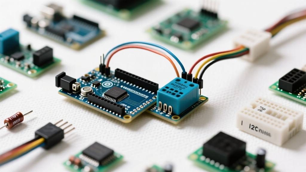
When integrating the PCA9685 into a multi-peripheral I2C bus (e.g., sharing the bus with a BME280 environmental sensor and an SSD1306 OLED), you must manage I2C pull-up resistors. Most breakout boards include 10kΩ pull-up resistors on the SDA and SCL lines.
If you connect three breakout boards, you place three 10kΩ resistors in parallel. Using the parallel resistance formula ($R_{total} = 1 / (1/R_1 + 1/R_2 + 1/R_3)$), the effective pull-up resistance drops to 3.33kΩ. While 3.33kΩ is generally acceptable for standard 100kHz I2C, it can cause signal degradation and data corruption if you push the bus to 400kHz Fast Mode, especially with long wires adding bus capacitance. If you experience I2C timeouts, physically remove the surface-mount pull-up resistors from the secondary modules, leaving only one 4.7kΩ or 10kΩ pull-up pair on the master bus.
Step-by-Step: Bulletproof Multi-Peripheral Wiring
- Power Distribution: Wire your 7.4V LiPo battery to both the Arduino's VIN pin and the input terminals of your 5V/9A Buck Converter.
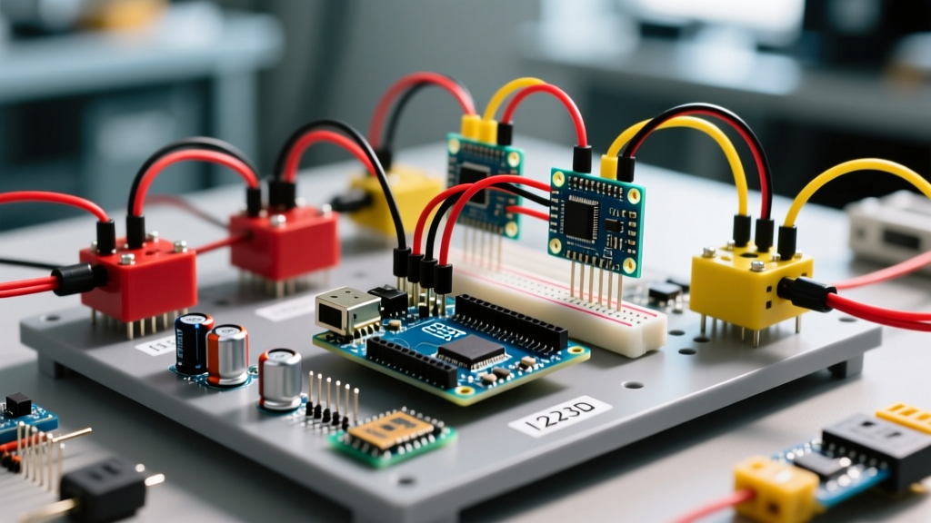
- Common Ground: Connect the Buck Converter GND, Arduino GND, and PCA9685 GND (green terminal block) together using a dedicated ground bus. Use 18 AWG silicone wire for power rails to prevent voltage drop under load.
- Servo Power Injection: Wire the 5V output of the Buck Converter to the V+ (red) terminal on the PCA9685. Do not route servo power through the PCB traces of the Arduino.
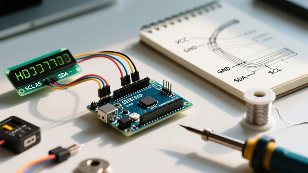
- I2C Bus Routing: Connect Arduino A4 (SDA) and A5 (SCL) to the PCA9685. Use 22 AWG twisted pair wire for I2C lines to minimize electromagnetic interference (EMI) from the high-current servo wires.
- Decoupling Capacitors: Solder or plug a 470µF to 1000µF electrolytic capacitor across the V+ and GND pins of the PCA9685 terminal block. For extreme high-torque setups, add a 100µF ceramic capacitor directly at the power leads of each individual MG996R servo to absorb micro-second voltage sags.
Edge Case Troubleshooting
Servo Jitter During Sensor Polling
If your servos twitch or jitter exactly when your Arduino polls an ultrasonic sensor or reads an analog pin, you are experiencing ground bounce or EMI. High-current servo motors generate massive electrical noise on the ground plane. Fix: Implement star-grounding. Run individual ground wires from the Arduino, the sensor suite, and the servo power supply to a single, central brass grounding screw or thick copper bus bar, rather than daisy-chaining grounds through breadboard rails.
Software Detaching for Power Saving
Even when using the PCA9685, servos will continuously draw holding current if they are under mechanical load. In battery-operated multi-peripheral setups, use the setPWM(pin, 0, 0) command to completely cut the PWM signal to a servo once it reaches its target position, allowing the internal servo amplifier to sleep and saving hundreds of milliamps per node.