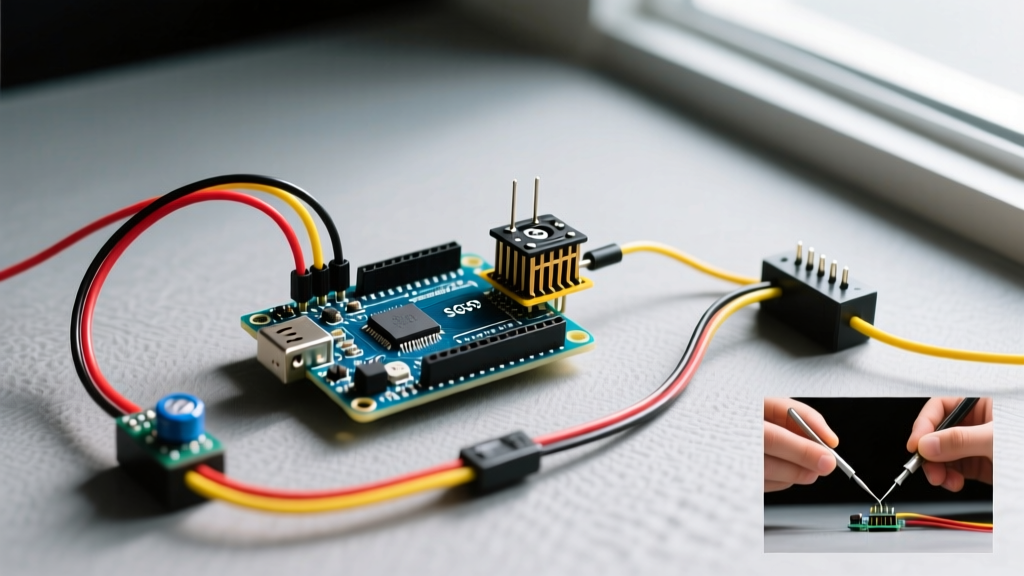

The Anatomy of Arduino Servo Control
Integrating an Arduino servo into your robotics, CNC, or automation project seems trivial until you hit the wall of hardware realities: microcontroller brownouts, PWM signal jitter, and timer conflicts. While the basic Sweep example gets a micro servo moving, scaling up to high-torque metal-gear servos requires a rigorous approach to power delivery and non-blocking code architecture. This guide dissects the exact wiring topologies, power budgeting, and C++ frameworks needed to run SG90, MG996R, and DS3218 servos flawlessly in 2026.
The 50Hz PWM Protocol Explained
Unlike standard DC motors, RC servos do not respond to analog voltage levels or standard high-frequency PWM duty cycles. They require a precise 50Hz Pulse Width Modulation (PWM) signal, which translates to a 20-millisecond (ms) period. Within that 20ms window, the width of the HIGH pulse dictates the shaft position:
- 1.0ms pulse: Commands the servo to 0 degrees.
- 1.5ms pulse: Commands the servo to the 90-degree center position.
- 2.0ms pulse: Commands the servo to 180 degrees.
The Arduino Servo.h library handles this timing automatically, but understanding this underlying protocol is critical when you begin debugging signal degradation over long wire runs or when migrating to hardware-timer interrupts in advanced embedded C++.
The Power Paradigm: Why USB Power Fails
The most common point of failure in beginner and intermediate projects is attempting to power high-torque servos directly from the Arduino's 5V pin or a standard PC USB port. A standard USB 2.0 port is limited to 500mA, and an Arduino's onboard linear voltage regulator will overheat and shut down if you pull more than ~400mA through the 5V pin. When a servo stalls or changes direction rapidly, it draws its peak stall current, causing a massive voltage sag that triggers the ATmega328P's brownout detection, resetting your microcontroller.
Servo Power & Torque Matrix
| Servo Model | Stall Current (5V) | Torque Rating | Gear Material | Power Source Requirement |
|---|---|---|---|---|
| TowerPro SG90 | ~750mA | 1.8 kg-cm | Nylon | Arduino 5V pin (Single servo only) |
| TowerPro MG996R | ~2.5A | 13 kg-cm | Brass/Steel | Dedicated 5V 3A Buck Converter |
| DS3218 (270°) | ~3.0A | 20 kg-cm | Full Steel | Dedicated 5V 5A Power Supply |
Modern Power Topologies for Multi-Servo Arrays
In 2026, relying on bulky benchtop linear power supplies for prototyping is outdated. For driving arrays of MG996R or DS3218 servos, the industry standard for rapid prototyping has shifted to USB-C Power Delivery (PD) Decoy Modules paired with high-efficiency buck converters.
- The USB-C PD Approach: Use a USB-C PD trigger board configured to request 5V at 3A (15W) from any modern laptop charger or power bank. This provides a clean, high-current 5V rail without the need for a dedicated wall-wart.
- The Step-Down Buck Approach: If your robot uses a 12V LiPo or SLA battery, use an LM2596 or MP1584EN buck converter. Critical Step: Use a multimeter to dial the potentiometer on the buck converter to exactly 5.05V before connecting it to your servos. This slight over-voltage compensates for the voltage drop across 20AWG wiring under heavy load.
Expert Wiring Rule: Never route the servo's power and ground through a breadboard. Breadboard traces are typically rated for only 1A to 2A. A stalling MG996R will melt the breadboard's internal copper clips, causing permanent resistance and voltage drops. Solder directly to a perfboard or use a dedicated servo power distribution board.
Step-by-Step Wiring for High-Torque Servos
To wire an MG996R safely to an Arduino Uno or Nano, follow this exact topology:
- Signal Wire (Orange/Yellow): Connect to Arduino Pin 6 (or any PWM pin except 9 and 10—see the Timer1 trap below).
- Power Wire (Red): Connect to the positive terminal of your dedicated 5V external power supply.
- Ground Wire (Brown/Black): Connect to the negative terminal of the external power supply AND to the Arduino's GND pin. This common ground is mandatory for the Arduino's PWM signal to have a valid reference voltage.
The Decoupling Capacitor Requirement
Servo motors generate massive electrical noise and inrush current. You must place a 470µF electrolytic capacitor (rated for at least 10V) and a 0.1µF ceramic capacitor in parallel across the VCC and GND lines as close to the servo connector as possible. The electrolytic cap handles the low-frequency inrush current during startup, while the ceramic cap shunts high-frequency EMI generated by the internal brushed DC motor, preventing it from corrupting the Arduino's ADC readings.
The Timer1 Hardware Trap
Most online tutorials omit a critical architectural detail: the standard Servo.h library on ATmega328P-based boards hijacks Timer1 to generate the precise 50Hz signals required by servos. The consequence? Hardware PWM is disabled on Pins 9 and 10. If your project also uses a motor driver (like the L298N) or an RGB LED relying on analogWrite() on those specific pins, they will fail silently or output erratic voltages. Always route your servo signal wires to Pins 3, 5, 6, or 11 to preserve Timer1 and Timer2 functionalities for other peripherals.
Arduino Servo Code: Non-Blocking Architecture
Using delay() to control a servo halts the entire microcontroller, preventing you from reading sensors or handling serial communication. Below is a production-ready, non-blocking state machine using millis() that smoothly sweeps a servo while leaving the main loop completely free for other tasks.
#include <Servo.h>

Servo primaryServo;
unsigned long previousMillis = 0;
const long interval = 20; // 50Hz update rate (20ms)
int currentAngle = 90;
int targetAngle = 90;
int stepDirection = 1;

void setup() {
  Serial.begin(115200);
  // Pin 6 avoids the Timer1 conflict on pins 9 and 10
  primaryServo.attach(6, 900, 2100);
  // 900 and 2100 define the min/max pulse widths in microseconds
  // Adjust these if your specific servo doesn't reach full 180 degrees
  primaryServo.write(currentAngle);
}

void loop() {
  // Non-blocking servo update loop
  unsigned long currentMillis = millis();
  if (currentMillis - previousMillis >= interval) {
    previousMillis = currentMillis;

    // Example logic: sweep between 10 and 170 degrees
    // Avoiding 0 and 180 prevents internal potentiometer binding
    currentAngle += stepDirection;
    if (currentAngle >= 170 || currentAngle <= 10) {
      stepDirection = -stepDirection;
    }
    primaryServo.write(currentAngle);
  }

  // Main loop remains unblocked
  // You can read ultrasonic sensors, parse Serial, or run PID loops here
  if (Serial.available() > 0) {
    int incomingTarget = Serial.parseInt();
    // Add logic to smoothly interpolate to incomingTarget
  }
}
Diagnostic Troubleshooting: Edge Cases and Failures
Even with perfect wiring, real-world deployments introduce edge cases. Here is how to diagnose and fix the most common servo anomalies:
- Servo Buzzing at Endstops: The internal potentiometer is dirty or the mechanical stop is slightly misaligned. Do not force the servo past 0 or 180 via code; limit your software range to 10-170 degrees to prevent internal gear binding and continuous stall current draw.
- Random Jitter During Operation: Usually caused by a noisy power supply or long, unshielded signal wires acting as antennas. Keep PWM signal wires under 12 inches. For longer runs, use a 74HC14 Schmitt trigger inverter to clean up degraded signal edges, or switch to a digital serial bus protocol like Dynamixel.
- Arduino Resetting Randomly: Classic brownout. The servo's inrush current during startup drops the 5V rail below the ATmega328P's brownout detection threshold (typically 4.3V). Verify your common ground, check your decoupling capacitors, and ensure your power supply can deliver at least 2.5A per MG996R.
- Slow or Sluggish Movement Under Load: The power supply voltage is sagging under load. Measure the voltage at the servo's VCC pin while it is moving. If it drops below 4.8V, you need thicker power wires (18 AWG) or a higher-capacity power supply.
Authoritative References
- Arduino Official Servo Library Documentation - Detailed breakdown of hardware timer dependencies, attach/detach methodologies, and pulse width parameters.
- Pololu Servo Motor Guide - Industry-standard engineering data on stall currents, PWM pulse width mapping, and mechanical load limits for RC servos.
- Arduino Docs: Servo Motors Explained - Comprehensive overview of internal feedback loops, decoupling requirements, and power distribution best practices.