
The Pin-Count Dilemma in 4-Digit Projects
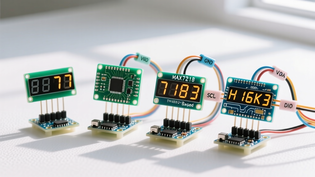
Driving 28 individual LEDs (four digits, seven segments each, plus decimal points) directly from a microcontroller is a pin-count nightmare. This is why the maker market is flooded with driver ICs and pre-assembled modules. However, when planning a 7 segment display 4 digit Arduino project, choosing the wrong interface can lead to severe CPU bottlenecks, flickering, or complex wiring harnesses. In this component comparison, we evaluate the four most common architectures available in 2026: bare multiplexed displays, TM1637 modules, MAX7219 SPI drivers, and HT16K33 I2C backpacks.
The Contenders: 4 Approaches to 4-Digit Displays
1. The Bare Multiplexed Display (5641AH / 3461BS)
The 5641AH (Common Cathode) and 3461BS (Common Anode) are raw, through-hole displays. They cost between $1.20 and $1.80 but require 12 microcontroller pins (8 for segments, 4 for digit commons). You must also add four switching transistors (like the 2N3904 NPN or 2N3906 PNP) and current-limiting resistors. While cheap, the CPU overhead for software multiplexing is immense.
2. The TM1637 Two-Wire Module
Priced around $1.50 to $2.50, the TM1637 module uses a proprietary, I2C-like protocol requiring only two data pins (DIO and CLK) plus power. It handles multiplexing in hardware and includes a dedicated colon LED, making it the default choice for digital clock projects. However, its non-standard protocol causes timing edge cases on faster 32-bit microcontrollers.
3. The MAX7219 SPI Driver Module (FC-104)
Costing $3.00 to $4.50, the MAX7219 is a true hardware multiplexer communicating via SPI (DIN, CS, CLK). It requires only three Arduino pins and features a built-in 10x10-bit PWM engine for hardware brightness control. It strictly requires Common Cathode displays and a single external current-setting resistor.
4. The HT16K33 I2C Backpack (Adafruit 1854)
At $10.95, the Adafruit HT16K33 backpack is the premium option. It uses standard I2C (just SDA and SCL pins), supports up to 16 unique addresses via onboard solder jumpers, and features a massive 16-byte RAM buffer. It is the only reliable choice if you plan to daisy-chain multiple 4-digit displays on a single I2C bus.
Head-to-Head Comparison Matrix
| Module / IC | Interface | MCU Pins | CPU Overhead | Brightness Control | Avg Cost (2026) |
|---|---|---|---|---|---|
| Bare 5641AH/3461BS | Direct / Multiplexed | 12 | High (Timer Interrupts) | Software PWM | $1.20 - $1.80 |
| TM1637 Module | Proprietary 2-Wire | 2 | Low (Blocking I/O) | 8-bit Hardware | $1.50 - $2.50 |
| MAX7219 (FC-104) | SPI | 3 | Near Zero | 10-bit Hardware | $3.00 - $4.50 |
| HT16K33 Backpack | I2C | 2 | Near Zero | 16-step Hardware | $10.95 |
Deep Dive: Engineering Edge Cases & Failure Modes
The Bare Display Trap: Multiplexing Timer Conflicts
When driving a bare 7 segment display 4 digit Arduino setup, beginners often attempt to multiplex using the delay() function inside the main loop. This guarantees severe flickering the moment you add sensor reading or serial communication. To achieve a flicker-free 60Hz refresh rate, you must use Timer1 interrupts to cycle the digit commons every 4 milliseconds. The open-source SevSeg library handles this elegantly, but it will conflict with any other libraries relying on Timer1 (such as the standard Servo library or certain IRremote implementations).
Calculating Peak Current for Bare Displays
A critical mistake is sizing resistors for continuous current rather than peak multiplexed current. A standard 5641AH has a continuous forward current of 20mA, but a peak forward current of 100mA. Because each digit is only illuminated 25% of the time (1/4 duty cycle), you must drive the segments at roughly 80mA peak to maintain perceived brightness. Assuming a 5V VCC, a 2.0V LED forward voltage, and a 0.2V transistor saturation voltage, the resistor calculation is:
R = (5.0V - 2.0V - 0.2V) / 0.080A = 35 ohms.
Use standard 39-ohm resistors. Using standard 220-ohm resistors will result in a dim, unreadable display in ambient light.
TM1637 Timing Edge Cases on 32-Bit MCUs
The TM1637 is not true I2C; it lacks clock stretching and ACK/NACK handshakes. Standard Arduino libraries bit-bang the protocol using microsecond delays calibrated for the 16MHz ATmega328P. If you migrate your project to an ESP32 (240MHz) or Raspberry Pi Pico (133MHz), the bit-bang transitions occur too fast for the TM1637 silicon to register, resulting in ghosting or entirely blank digits. The fix requires modifying the library source to inject delayMicroseconds(50) between clock transitions.
MAX7219 Power Delivery & Decoupling
The MAX7219 switches high currents rapidly across its segment pins. According to the official Analog Devices MAX7219 datasheet, long jumper wires introduce parasitic inductance that causes voltage spikes on the VCC rail. This inductive kickback frequently trips the Arduino brown-out detector, causing random resets. You must solder a 10uF electrolytic capacitor and a 0.1uF ceramic capacitor directly across the VCC and GND pins on the FC-104 module, not just rely on the Arduino onboard regulation.
Logic Level Shifting for 3.3V Microcontrollers
As the maker community shifts toward 3.3V logic ecosystems like the ESP32-S3 and Raspberry Pi Pico, driving 5V-tolerant displays introduces new hurdles. The TM1637 and MAX7219 generally recognize 3.3V as a logic HIGH, but signal integrity degrades over jumper wires longer than 15cm. If you experience random digit dropping on an ESP32, use a bidirectional logic level converter (like the BSS138 MOSFET-based modules costing ~$1.50) on the CLK and DIO lines. The HT16K33, being a native 3.3V I2C device, completely bypasses this issue, further justifying its premium price tag for modern IoT sensor nodes.
Optical Considerations: Diffused vs. Clear Epoxy
When sourcing bare displays or modules, pay attention to the epoxy coating. Clear epoxy displays offer sharper, more intense light output but suffer from severe cross-talk and glare in brightly lit rooms. Diffused (milky white) epoxy scatters the light evenly across the segment face, providing superior viewing angles and eliminating the hotspot effect directly above the LED die. For automotive or outdoor enclosures, always specify diffused variants and pair them with a polarized acrylic faceplate to maintain contrast ratios above 50:1 in direct sunlight.
Final Verdict: Which Should You Choose?
- Choose Bare (5641AH) only if you are designing a custom PCB, need to minimize BOM costs below $2.00, and have spare Timer1 interrupts available.
- Choose TM1637 for simple, low-cost digital clocks or timers on 8-bit Arduinos where you only have two spare GPIO pins and need the built-in colon LED.
- Choose MAX7219 for high-brightness industrial dashboards, scoreboards, or sensor readouts where zero CPU overhead and precise 10-bit hardware dimming are mandatory.
- Choose HT16K33 if you are building complex I2C sensor networks. As noted in the Adafruit LED Backpack guide, the ability to chain up to 16 displays on a single I2C bus makes it unbeatable for multi-zone environmental monitoring panels.