
Why Choose the TMP36 for Your Arduino Project?
When beginners start exploring environmental monitoring, the temperature sensor TMP36 Arduino combination is often the first analog integration they attempt. Unlike digital sensors such as the DS18B20 that require specific 1-Wire libraries, the TMP36 is a precision, low-voltage, centigrade temperature sensor that outputs an analog voltage directly proportional to the ambient temperature. Manufactured by Analog Devices, the TMP36 operates on a single supply from 2.7V to 5.5V, making it perfectly compatible with both 5V Arduino Uno boards and 3.3V boards like the Arduino Nano 33 IoT or ESP32 microcontrollers.
The defining feature of the TMP36 is its 500mV DC offset. While the similar LM35 outputs 0V at 0°C, the TMP36 outputs 0.5V at 0°C. This crucial design choice allows the sensor to measure sub-zero temperatures down to -40°C without requiring a negative power supply rail—a massive advantage for battery-powered, single-supply DIY projects.
Authentic vs. Clone: Navigating the 2026 Component Market
Before wiring your circuit, it is vital to address component sourcing. As of 2026, the market is heavily saturated with counterfeit or mislabeled sensors. Genuine Analog Devices TMP36GT9Z (TO-92 package) chips typically cost between $1.80 and $2.50 each on authorized distributors like Mouser or DigiKey. Conversely, bulk packs found on Amazon or AliExpress (e.g., 20 sensors for $5) are frequently out-of-spec clones or, worse, LM35 sensors mislabeled as TMP36s. Using an LM35 with TMP36 math will result in readings that are off by roughly 50°C.
| Parameter | Specification | Notes |
|---|---|---|
| Supply Voltage (Vs) | 2.7V to 5.5V | Exceeding 5.5V will destroy the IC. |
| Temperature Range | -40°C to +125°C | Accuracy degrades above 100°C. |
| Scale Factor | 10 mV/°C | Linear output. |
| Offset Voltage | 500 mV | Allows sub-zero measurement. |
| Accuracy | ±1°C (typical at 25°C) | ±2°C over full range. |
| Quiescent Current | 50 µA | Extremely low power draw. |
Hardware Pinout and Wiring Diagram
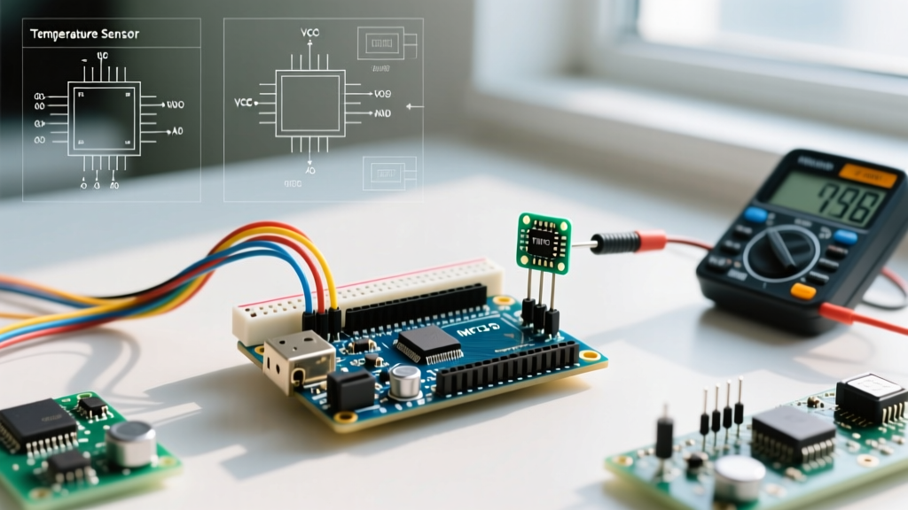
The TMP36 typically comes in a TO-92 package, which looks identical to a standard 2N2222 transistor. To correctly identify the pins, hold the sensor so the flat face is pointing toward you and the leads are pointing downward.
- Pin 1 (Left): VCC (Connect to Arduino 5V or 3.3V)
- Pin 2 (Middle): VOUT (Connect to Arduino Analog Pin A0)
- Pin 3 (Right): GND (Connect to Arduino GND)
⚠️ CRITICAL WARNING: Never wire the TMP36 backward. If you accidentally swap VCC and GND while the circuit is powered, the sensor will draw maximum current, become hot enough to burn your finger within seconds, and permanently fail. Always double-check the flat-side orientation before applying power.
The Math: Converting ADC Values to Celsius
The Arduino's analog-to-digital converter (ADC) reads voltages and maps them to a digital number. On a standard 10-bit ADC (like the ATmega328P on the Uno), the reading ranges from 0 to 1023. To extract the actual temperature, we must reverse-engineer the voltage.
First, calculate the voltage at the analog pin:
Voltage = (ADC_Reading * Reference_Voltage) / 1024.0
Assuming a 5V reference voltage, each ADC step represents approximately 4.88 mV (5000mV / 1024). Next, we apply the TMP36 transfer function. Since the sensor outputs 500mV at 0°C and scales at 10mV per degree Celsius, the formula is:
Temperature (°C) = (Voltage_in_mV - 500) / 10.0
If you are using a 3.3V Arduino board, you must change the Reference_Voltage to 3.3 (or 3300mV) in your calculations, otherwise your temperature readings will be wildly inaccurate.
Production-Ready Arduino Code with Oversampling
Beginner tutorials often use a single analogRead() call. However, the Arduino's ADC is susceptible to electrical noise from USB power supplies and nearby digital switching. To achieve professional-grade stability, we use oversampling—taking multiple rapid readings and averaging them.
// TMP36 Oversampling Sketch for Arduino Uno (5V Logic)
const int sensorPin = A0;
const float referenceVoltage = 5.0; // Change to 3.3 for 3.3V boards
const int numSamples = 20;

void setup() {
  Serial.begin(115200);
  analogReference(DEFAULT); // Ensure 5V reference on Uno
}

void loop() {
  float temperatureC = readTMP36();
  float temperatureF = (temperatureC * 9.0 / 5.0) + 32.0;

  Serial.print("Temp: ");
  Serial.print(temperatureC, 2);
  Serial.print(" °C | ");
  Serial.print(temperatureF, 2);
  Serial.println(" °F");

  delay(1000); // 1 second update rate
}

float readTMP36() {
  long sum = 0;
  for (int i = 0; i < numSamples; i++) {
    sum += analogRead(sensorPin);
    delay(2); // Small delay for ADC settling
  }

  float averageADC = (float)sum / numSamples;

  // Convert ADC to Voltage (in millivolts for precision)
  float voltageMV = (averageADC * referenceVoltage * 1000.0) / 1024.0;

  // Convert Voltage to Celsius
  float tempC = (voltageMV - 500.0) / 10.0;

  return tempC;
}
Advanced Troubleshooting and Edge Cases
Even with perfect code, analog sensors present unique hardware challenges. Here is how to solve the most common edge cases encountered in the field.
1. Noisy Readings and the Decoupling Capacitor
If your serial monitor shows temperatures fluctuating by 1-2°C rapidly, you are experiencing ADC noise or power rail ripple. The TMP36 datasheet explicitly recommends placing a 0.1µF (100nF) ceramic capacitor between the VCC and GND pins, as physically close to the sensor body as possible. This acts as a local energy reservoir, filtering out high-frequency noise before it reaches the sensor's internal op-amps.
2. Self-Heating Errors
Because the TMP36 draws only 50 µA, self-heating is generally negligible in still air. However, if you mount the sensor inside an enclosed 3D-printed PLA case near a voltage regulator or an actively switching motor driver, the ambient heat will skew readings. Always route the sensor outside of enclosures or use a thermally isolated breakout board with long jumper wires to distance the TO-92 package from heat-generating components.
3. Long Wire Runs and Signal Degradation
The TMP36 has a relatively high output impedance compared to digital sensors. If you run wires longer than 1 meter (3 feet) from the sensor to the Arduino, the wire acts as an antenna, picking up 50/60Hz mains hum. For runs exceeding 1 meter, you must either use a shielded twisted-pair cable with the shield tied to GND at the Arduino end, or buffer the analog signal using an op-amp voltage follower circuit at the sensor head.
Authoritative References
- Analog Devices TMP35/TMP36/TMP37 Official Datasheet - Comprehensive electrical characteristics, transfer functions, and application circuits.
- Arduino Official analogRead() Documentation - Details on ADC resolution, reference voltages, and hardware multiplexing limits.