
The Hardware Reality: Why Standard Tutorials Fail
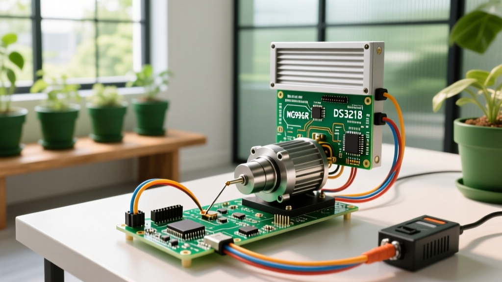
Most introductory electronics guides stop at the SG90 micro servo. While excellent for learning basic pulse-width modulation (PWM), the SG90 is entirely inadequate for real-world robotics, automated solar trackers, or heavy-duty camera gimbals. When you step up to high-torque metal-gear servos like the TowerPro MG996R (13 kg·cm, ~$10) or the DS3218 (20 kg·cm, ~$25), the standard Servo.h library and Arduino 5V power rails will inevitably fail.
When coding Arduino servo arrays for heavy-duty applications, engineers face three primary failure modes: thermal shutdown of the Arduino's linear voltage regulator, PWM signal jitter causing mechanical oscillation, and gear-stripping due to instantaneous velocity changes. This guide bridges the gap between hobbyist tutorials and production-grade robotic joint control, focusing on power architecture, hardware PWM offloading, and trapezoidal motion profiling.
Power Architecture: Surviving the Current Spike
The most common mistake when wiring high-torque servos is powering them directly from the Arduino's 5V pin. A standard MG996R can draw up to 2.5A during stall or rapid direction reversal. The Arduino Uno's onboard linear regulator is typically rated for a maximum of 800mA (and practically much less without a heatsink). Attempting to pull 2.5A will cause immediate thermal shutdown, brownout resets, or permanent damage to the MCU.
Sizing Your Battery Eliminator Circuit (BEC)
For real-world deployments, you must use a dedicated step-down buck converter or an RC-grade UBEC (Universal Battery Eliminator Circuit). According to Pololu's RC Servo Motor guidelines, you must size your power supply not for the continuous running current, but for the absolute peak stall current of all servos moving simultaneously.
| Servo Model | Stall Torque (6V) | Peak Stall Current | Recommended BEC Rating | Estimated 2026 Unit Cost |
|---|---|---|---|---|
| TowerPro MG996R | 13 kg·cm | ~2.5A | 5V / 3A Continuous | $8 - $12 |
| DS3218 (270°) | 20 kg·cm | ~3.0A | 6V / 5A Continuous | $22 - $28 |
| Feetech SCS15 (Smart) | 15 kg·cm | ~1.8A | 7.4V / 3A (Serial Bus) | $18 - $24 |
Decoupling is Mandatory: Even with a robust 5A BEC, long wire runs introduce inductance. When a high-torque servo reverses direction, it demands instantaneous current. You must solder a 1000µF to 2200µF low-ESR electrolytic capacitor directly across the VCC and GND pins at the servo distribution board. This acts as a local energy reservoir, preventing voltage sags that cause the Arduino to reset.
Eliminating PWM Jitter with Hardware Offloading
The standard Arduino Servo Library relies on the MCU's Timer1 to generate 50Hz PWM signals via software interrupts. In a simple blink-and-sweep sketch, this works fine. However, in a complex robotic system where the Arduino is simultaneously reading I2C IMUs, processing PID loops, and handling serial telemetry, interrupt latency occurs.
A delay of just 20 microseconds in the software interrupt translates to a physical position jump. On a 20 kg·cm servo, this microsecond jitter manifests as a high-frequency mechanical vibration that destroys gears and strips potentiometer wipers over time.
The PCA9685 Solution
To achieve rock-solid positional accuracy, you must offload PWM generation to dedicated hardware. The PCA9685 16-channel I2C PWM driver is the industry standard for this task. It features a dedicated 25MHz internal oscillator and handles pulse timing completely independent of the Arduino's main loop. As detailed in the Adafruit PCA9685 integration guide, this chip communicates via I2C (default address 0x40) and updates all 16 channels simultaneously via a latch pin, ensuring perfectly synchronized multi-axis movements.
Pro-Tip for I2C Stability: The PCA9685 operates on 3.3V logic internally but tolerates 5V I2C lines. However, if you are running long I2C cables (over 30cm) to a robotic arm base, you must use a dedicated I2C bus extender (like the P82B715) or active pull-up resistors (4.7kΩ to 3.3V) to prevent signal degradation and phantom servo twitches.
Writing Smooth Acceleration Profiles (Trapezoidal Motion)
Sending a raw writeMicroseconds(2000) command to a high-torque servo commands it to move at maximum velocity instantly. The resulting inertia can snap 3D-printed PLA/PETG brackets and strip brass gears. Real-world coding requires implementing a trapezoidal velocity profile to ease the servo into and out of motion.
Algorithm Implementation Steps
- Calculate Delta: Determine the absolute distance between the current position and the target position in microseconds.
- Divide the Profile: Split the movement into three phases: Acceleration (first 30% of distance), Cruising (middle 40%), and Deceleration (final 30%).
- Dynamic Delay Mapping: Instead of a fixed
delay(15)between step increments, map the delay inversely to the velocity curve. Use a cosine interpolation function for the acceleration and deceleration phases to achieve S-curve (jerk-limited) motion. - Non-Blocking Execution: Never use
delay()in the motion loop. Usemillis()or hardware timers to step the servo position incrementally, allowing the main loop to continue processing sensor feedback.
By calculating the intermediate microsecond targets and feeding them to the PCA9685 at a consistent 20ms interval, the servo accelerates smoothly, reaches a safe cruising speed, and gently decelerates into the target detent. This reduces peak current draw by up to 40% and drastically extends the mechanical lifespan of the joint.
Real-World Troubleshooting & Edge Cases
Even with perfect code and hardware PWM, real-world environments introduce noise. Here are the most common edge cases encountered in 2026 robotic deployments and how to resolve them:
- Ground Loop Oscillation: If your servo twitches rhythmically, you likely have a ground loop. Ensure the Arduino GND, BEC GND, and Servo GND are tied together at a single central star-ground point. Do not daisy-chain the ground wire through the servo signal harness.
- Potentiometer Deadband Hunting: Standard analog servos have a mechanical deadband. If your code commands a position that falls inside this deadband, the servo will 'hunt' (oscillate back and forth). Implement a software deadband in your C++ class: if the absolute difference between the current target and new target is less than 15 microseconds, ignore the command.
- Thermal Rollback in Continuous Use: High-torque servos generating holding torque (e.g., a robotic arm holding a weight extended) will overheat the internal DC motor windings. Implement a software timeout that relaxes the PWM signal (turns off the driver FET) if the position error remains below 1 degree for more than 2 seconds.
Summary
Transitioning from micro-servos to high-torque industrial or robotic servos requires a fundamental shift in both hardware architecture and software design. By utilizing dedicated UBEC power supplies with low-ESR decoupling, offloading PWM generation to a PCA9685 driver, and coding trapezoidal motion profiles, you transform a jittery, unreliable prototype into a robust, production-ready robotic system. Mastering these real-world coding Arduino servo techniques is what separates fragile hobby projects from reliable electromechanical engineering.