
The Evolution of the Arduino Stepper Motor Controller
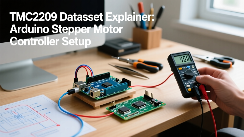
When building precision CNC routers, camera sliders, or 3D printers in 2026, the days of relying on the loud, vibration-heavy A4988 or DRV8825 chips are over. The Trinamic TMC2209 has become the gold standard for any high-performance Arduino stepper motor controller setup. However, simply dropping a TMC2209 breakout board onto a breadboard and sending step pulses only utilizes a fraction of its capabilities. To truly eliminate mid-band resonance, enable sensorless homing, and optimize thermal performance, you must understand the silicon itself. This datasheet explainer breaks down the critical registers, electrical limits, and timing diagrams required to master this advanced driver.
Core Electrical Specifications & Limits
Before wiring your microcontroller, you must respect the absolute maximum ratings outlined in the official Trinamic TMC2209 documentation. Pushing beyond these limits will result in catastrophic silicon failure, often shorting the VM pin directly to ground.
| Parameter | Symbol | Min | Typical | Max | Notes |
|---|---|---|---|---|---|
| Motor Supply Voltage | V_M | 4.75V | 12V / 24V | 29V | Do not exceed 29V; 24V systems should use a buck converter for safety margin. |
| Logic Supply Voltage | V_IO | 3.0V | 3.3V / 5V | 5.5V | Match to your Arduino/ESP32 logic level. |
| RMS Coil Current | I_RMS | - | 1.2A | 2.0A | 2.0A requires active cooling and a 0.11Ω sense resistor. |
| Microstep Resolution | - | - | 256 | 256 | Internal interpolator smooths STEP/DIR inputs up to 256 μsteps. |
Pinout Decoded: Standalone vs. UART Configuration
The TMC2209 supports two distinct operational modes. Understanding which mode you are using dictates how you wire your Arduino stepper motor controller circuit.
1. Standalone Mode (Legacy STEP/DIR)
In standalone mode, the driver behaves like a traditional A4988. Microstepping is configured by pulling the MS1 and MS2 pins high or low. Current is set manually via the VREF potentiometer. While functional, this mode completely disables UART telemetry, StallGuard4, and dynamic current scaling.
2. UART Mode (The Modern Standard)
By utilizing the PDN_UART pin, your microcontroller can read and write directly to the TMC2209’s internal registers.
Wiring Rule: The TMC2209 uses a single-wire UART interface. You must wire the PDN_UART pin to an Arduino digital pin through a 1kΩ series resistor, and add a 10kΩ pull-up resistor to V_IO. This prevents logic contention when the driver transmits data back to the Arduino.
Expert Tip: If you are using an ESP32 or Arduino Mega, utilize HardwareSerial (e.g., Serial1) rather than SoftwareSerial. The TMC2209 UART requires precise timing at 115200 baud, and SoftwareSerial often drops bytes during high-speed stepper interrupt routines.
Mastering StealthChop2 and SpreadCycle Transitions
The datasheet details two distinct chopper modes. StealthChop2 uses voltage PWM to drive the coils, resulting in near-zero audible noise at low to medium speeds. SpreadCycle uses current-based hysteresis chopping, providing higher torque and better high-speed stability, but with audible whining.
The true power of the TMC2209 lies in the TPWMTHRS register, which dictates the velocity threshold where the chip automatically transitions between the two modes.
- TPWMTHRS = 0: StealthChop2 is active at all speeds (risk of losing steps at high RPM).
- TPWMTHRS = 255 (Default): Transition occurs at a moderate velocity.
- TPWMTHRS = 65535: SpreadCycle is active at all speeds (StealthChop disabled).
Actionable Setup: For a typical NEMA 17 motor on a 20-tooth GT2 pulley, set TPWMTHRS to roughly 450 (equivalent to ~300mm/s). This keeps the motor silent during slow panning or 3D printing perimeters, but seamlessly shifts to SpreadCycle for rapid travel moves to prevent missed steps.
Current Scaling: VREF Potentiometer vs. UART Registers
Many beginners burn out their motors by blindly turning the VREF potentiometer. When using UART, the potentiometer is largely bypassed for dynamic current control, governed instead by the IHOLD_IRUN register.
The UART Current Formula
The datasheet defines the relationship between the IRUN register (0-31) and the RMS current based on your sense resistor (R_SENSE). Assuming a standard 0.11Ω sense resistor and a 5V logic reference:
I_RMS = (IRUN + 1) / 32 * (V_FS / R_SENSE) * 0.707
Where V_FS is the full-scale voltage (typically 0.325V for the TMC2209).
Practical Example: To drive a standard 1.5A NEMA 17 motor safely:
Set IRUN = 16 (approx 1.5A RMS) and IHOLD = 6 (approx 0.5A RMS for holding torque when stationary). This dynamic reduction prevents the motor from overheating during idle periods, a feature impossible on older drivers.
Sensorless Homing with StallGuard4
Eliminating physical limit switches saves wiring complexity and reduces mechanical failure points. The TMC2209’s StallGuard4 feature measures the back-EMF of the motor to detect mechanical load. When the axis hits a hard stop, the load spikes, and the driver pulls the DIAG pin HIGH.
To implement this in your Arduino stepper motor controller code via the TMCStepper Library:
- Set the
SGTHRS(StallGuard Threshold) register. A value of 100 is a good starting point for NEMA 17s. - Ensure the motor is running in SpreadCycle mode (StallGuard does not work reliably in StealthChop).
- Route the
DIAGpin to an Arduino hardware interrupt pin (e.g., Pin 2 or 3 on an Uno). - Reduce homing speed to 50-100mm/s. StallGuard requires a minimum step frequency to accurately calculate the load angle.
Thermal Management and Failure Modes
The datasheet outlines strict thermal protection mechanisms. The silicon junction temperature (T_J) is monitored continuously.
- 120°C (Pre-warning): The driver sets the
OTPW(Overtemperature Pre-Warning) flag in theDRV_STATUSregister. Your Arduino code should read this flag and automatically reduceIRUNby 20% to prevent shutdown. - 150°C (Shutdown): The driver disables the H-bridge to save the silicon. The motor will freewheel, resulting in a lost position. The driver will not re-enable until the temperature drops below 120°C.
Hardware Reality Check: In 2026, the market is flooded with $2.50 clone TMC2209 boards. While clones often work for basic STEP/DIR, their internal thermal sensors are frequently uncalibrated, and their StealthChop PWM logic generates excess heat. For mission-critical CNC or continuous-duty 3D printing, invest $5.50–$7.00 in genuine Watterott or BigTreeTech (BTT) boards utilizing authentic Trinamic/Analog Devices silicon.
Arduino Implementation Strategy
For robust firmware, avoid writing raw UART byte arrays. Instead, leverage established frameworks. If you are building a custom Arduino-based motion controller, the Marlin firmware documentation provides an excellent reference for register initialization sequences. For standalone Arduino sketches, initialize the driver using the TMCStepper library, explicitly defining the R_SENSE value (usually 0.11f) in the constructor to ensure the library's current calculation math aligns with your physical hardware.
Frequently Asked Questions
Can I use a 5V Arduino with the TMC2209?
Yes. The TMC2209 logic pins are 5V tolerant. However, you must ensure the V_IO pin on the breakout board is powered by 5V, and you must use the 1kΩ series resistor on the UART TX line to prevent back-feeding voltage into the driver's RX buffer.
Why is my motor vibrating loudly in StealthChop mode?
StealthChop2 can suffer from mid-band resonance if the TPWMTHRS threshold is set incorrectly, or if the motor's inductance is too high. If using a high-inductance motor (e.g., >4mH), lower the supply voltage to 12V or switch to SpreadCycle for the problematic velocity range.
What is the minimum step pulse width?
The datasheet specifies a minimum STEP pulse high/low time of 100ns. Any standard AVR or ARM-based Arduino running at 16MHz or higher will easily meet this timing requirement without software delays.