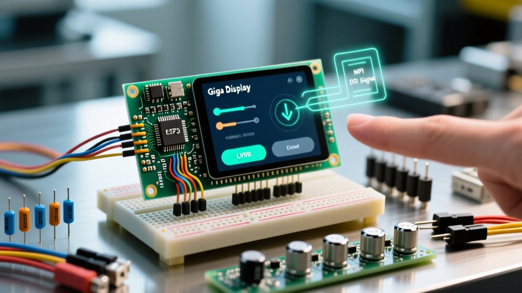

Architecting HMI Solutions with the Arduino Giga Display Shield
The transition from simple SPI-based TFTs to high-resolution, hardware-accelerated displays marks a major leap in embedded systems design. The Arduino Giga Display Shield represents this leap, pairing a 4.53-inch, 720x720 IPS panel with the dual-core STM32H747XI microcontroller found on the Giga R1 WiFi. Unlike legacy shields that rely on bit-banged SPI or slow 8-bit parallel interfaces, this shield utilizes a MIPI DSI (Display Serial Interface) host controller and Direct Memory Access (DMA) to push pixels at 60 FPS without burdening the CPU.
However, this hardware sophistication demands a precise software stack. Standard Adafruit_GFX SPI drivers are entirely incompatible here. As of 2026, successfully deploying the Arduino Giga Display Shield requires a deep understanding of the ST HAL (Hardware Abstraction Layer), external SDRAM memory mapping, and the Light and Versatile Graphics Library (LVGL). This guide provides the definitive library and driver setup for professional-grade HMI (Human-Machine Interface) development.
Hardware-to-Software Pinout & Bus Matrix
Before initializing any libraries, it is critical to understand how the shield physically interfaces with the Giga R1 WiFi. Misconfiguring these buses is the leading cause of initialization timeouts.
| Subsystem | Interface / Protocol | Key Pins / Addresses | Driver Requirement |
|---|---|---|---|
| MIPI DSI Video | MIPI DSI Host (4 Data Lanes) | DSI_D0P/N to DSI_D3P/N, DSI_CLK | ST HAL DSI Host + LTDC |
| Capacitive Touch | I2C1 (Fast Mode Plus) | SDA (PB9), SCL (PB8), INT (PK1) | Goodix GT911 I2C Driver |
| Backlight Control | PWM (TIM3) | PA13 (Backlight Enable/PWM) | Hardware PWM > 15kHz |
| External RAM | FMC (Flexible Memory Controller) | SDRAM Bank 1 (IS42S16160J) | SDRAM HAL Initialization |
The Core Library Stack
To drive the Arduino Giga Display Shield, you must install three distinct libraries via the Arduino IDE Library Manager or PlatformIO. Relying on outdated forks will result in memory allocation faults.
1. Arduino_GigaDisplay_GFX
This is the foundational wrapper maintained by Arduino. It abstracts the complex STMicroelectronics LTDC (LCD-TFT Display Controller) and DSI Host initialization into a familiar GFX-like API. It handles the PLL clock configuration required to generate the precise pixel clock (typically around 35-40 MHz for a 720x720 panel at 60Hz).
2. Arduino_GigaDisplayTouch
The shield uses the Goodix GT911 capacitive touch controller. This library manages the I2C communication and the highly specific hardware reset sequence the GT911 requires to latch its I2C address (0x5D or 0x14) upon boot.
3. LVGL (Light and Versatile Graphics Library)
For complex UIs, raw GFX drawing is insufficient. LVGL (version 8.3 or 9.x) provides widgets, anti-aliasing, and animation engines. According to the official LVGL documentation, integrating LVGL with custom MIPI DSI displays requires mapping the display flush callback directly to the DMA-linked frame buffers.
Advanced Memory Management: SRAM vs. SDRAM
The most common failure mode when deploying the Arduino Giga Display Shield is an SRAM overflow. A single 720x720 frame buffer in RGB565 (16-bit color) consumes exactly 1,036,800 bytes (approx. 1 MB). The STM32H747XI has 1 MB of internal SRAM, but much of this is reserved for the Mbed OS RTOS, Wi-Fi/BLE stacks, and CPU cache.
Expert Directive: Never allocate your LVGL draw buffers in internal SRAM. You must route frame buffers to the shield's onboard 8MB SDRAM (IS42S16160J-6BLI) mapped at address 0x70000000.
Here is the architectural flow for double-buffering in external SDRAM:
- Initialize FMC: Call
SDRAM.begin()before any display functions to configure the FMC timing registers (CAS latency, RAS precharge) for the SDRAM chip. - Allocate Buffers: Define two buffers of at least 1/10th the screen size (e.g., 720 x 72 x 2 bytes = 103,680 bytes each) using pointers cast to the SDRAM base address.
- Configure LVGL: Pass these SDRAM pointers to
lv_disp_draw_buf_init(). This allows LVGL to render the next frame chunk while the DMA controller asynchronously pushes the previous chunk to the MIPI DSI FIFO.
Driver Initialization & The Flush Callback
The bridge between LVGL and the Arduino Giga Display Shield is the flush callback. This function is triggered by LVGL whenever a UI element needs updating.
void my_disp_flush(lv_disp_drv_t *disp, const lv_area_t *area, lv_color_t *color_p) {
    // Calculate the exact pixel offset for the partial update
    uint32_t w = (area->x2 - area->x1 + 1);
    uint32_t h = (area->y2 - area->y1 + 1);

    // Push the buffer to the MIPI DSI via the GFX wrapper
    // This triggers the DMA transfer to the LTDC layer
    gfx.drawRGBBitmap(area->x1, area->y1, (uint16_t*)color_p, w, h);

    // Signal LVGL that the DMA transfer has been queued
    lv_disp_flush_ready(disp);
}
Notice the use of drawRGBBitmap. Under the hood, the Arduino_GigaDisplay_GFX library maps this call to the LTDC layer 1 frame buffer address, ensuring zero-copy memory transfers where possible.
Critical Edge Cases & Troubleshooting
When integrating the Arduino Giga Display Shield into industrial or commercial enclosures, you will encounter edge cases that standard tutorials ignore. Below are the solutions to the most persistent hardware-software conflicts.
1. Touch Controller I2C Starvation
The Goodix GT911 is notoriously sensitive to I2C bus noise and boot-state timing. If the Giga R1 WiFi boots too quickly and polls the I2C bus before the GT911's internal firmware has initialized (approx. 50ms post-power), the touch controller will lock up and fail to acknowledge its address.
The Fix: Implement a hardware reset sequence in your setup() loop before calling Wire.begin(). Pull the GT911 reset pin LOW for 10ms, then HIGH, and enforce a delay(100) to allow the touch IC to boot its internal ROM.
2. LVGL Tick Drift Under RTOS Load
LVGL relies on a monotonic tick to handle animations and timeouts. Most beginners use lv_tick_inc(5) inside the main loop(). However, the Giga R1 runs Mbed OS. If the Wi-Fi stack or the Cortex-M4 core triggers a high-priority interrupt, the main loop stalls, causing LVGL animations to stutter or freeze.
The Fix: Offload the LVGL tick to a dedicated hardware timer. Configure one of the STM32's hardware timers to fire an interrupt exactly every 2ms, and place lv_tick_inc(2) inside that Interrupt Service Routine (ISR). This guarantees UI timing remains decoupled from RTOS thread scheduling.
3. Backlight PWM Interference
The shield's backlight LED driver requires a PWM signal. Using the default Arduino analogWrite() function generates a PWM frequency of roughly 1kHz to 2kHz. This low frequency can cause visible flickering on camera sensors (a major issue for machine vision kiosks) and can introduce switching noise into the MIPI DSI PLL.
The Fix: Reconfigure the timer prescaler to push the backlight PWM frequency to at least 20kHz. Using the advanced timer functions in the STM32 HAL, set the frequency to 20,000 Hz to ensure smooth dimming and eliminate electromagnetic interference (EMI) with the DSI data lanes.
Sourcing and Cost Considerations for 2026
When budgeting for a production run or a high-end prototype, factor in the current market pricing. As of early 2026, the Arduino Giga Display Shield retails for approximately $68 to $75 USD. The required Giga R1 WiFi board sits between $85 and $95 USD. This brings the core HMI processing cost to roughly $160 USD. While this is a premium price point compared to ESP32-S3 driven SPI displays, the inclusion of the STM32H747XI, 8MB SDRAM, and hardware-accelerated MIPI DSI justifies the cost for applications requiring complex LVGL animations, real-time FFT graphing, or secure TLS Wi-Fi communications.
For complete hardware schematics and official pinout diagrams, always refer to the Arduino Giga Display Shield Documentation. Furthermore, developers pushing the Cortex-M7 core to its limits should consult the STMicroelectronics STM32H747XI reference materials for deep-dive register configurations regarding the LTDC and DMA2D chrom-art accelerators.