
Integrating environmental or spatial sensors into a microcontroller project requires a reliable human-machine interface (HMI). While OLED and TFT screens offer high resolution, they are often overkill for simple numerical telemetry like temperature, humidity, or distance. This is where the Arduino 4 digit 7 segment display excels. It provides high-visibility, low-latency numerical readouts that can be read from across a room or in direct sunlight. However, driving these displays directly from a microcontroller's GPIO pins is a notorious trap for beginners, leading to flickering readouts and blocked sensor polling loops.
In this sensor integration tutorial, we will bypass the pitfalls of direct multiplexing. We will explore the two industry-standard driver ICs—the TM1637 and the MAX7219—and demonstrate how to architect a non-blocking firmware loop that polls a DHT22 temperature sensor while maintaining a rock-solid display update rate.
The Multiplexing Trap: Why You Need a Display Driver
A standard 4-digit 7-segment display has 12 pins (8 segments including the decimal point, plus 4 common cathode/anode pins). To drive this directly, an Arduino Uno must rapidly cycle through each digit, illuminating the correct segments for roughly 2 milliseconds before switching to the next digit. This technique, called persistence of vision multiplexing, requires the microcontroller to do nothing else but manage the display.
If your code includes a blocking function—such as delay() or a slow sensor read—the multiplexing halts. The result is either a severely flickering display or a single digit frozen at maximum brightness, which can quickly burn out the LED junction. By offloading the refresh cycle to a dedicated driver IC, the Arduino only needs to transmit data when the sensor value actually changes.
Hardware Matrix: TM1637 vs. MAX7219
When sourcing an Arduino 4 digit 7 segment display module in 2026, you will primarily encounter two driver architectures. Here is how they compare for sensor integration projects:
| Feature | TM1637 (e.g., FC-113 Module) | MAX7219 (Generic SPI Module) | Direct GPIO Multiplexing |
|---|---|---|---|
| Interface | Custom 2-Wire (CLK, DIO) | SPI (DIN, CLK, CS) | 12x GPIO Pins |
| Internal Refresh RAM | Yes (Hardware handled) | Yes (Hardware handled) | No (Software handled) |
| Max Current Draw | ~80mA (at full brightness) | ~320mA (all segments lit) | ~120mA (limited by GPIO) |
| Avg. Module Cost (2026) | $1.50 - $2.50 | $3.00 - $5.00 | $1.00 (Raw component) |
| Best Use Case | Simple temp/humidity readouts | Multi-sensor dashboards, daisy-chaining | Learning basic electronics |
Expert Insight: The TM1637 is frequently mislabeled as an I2C device by amateur tutorial sites. It is not I2C. It uses a custom 2-wire UART-like protocol with a specific ACK bit. Attempting to scan it with a standard I2C scanner sketch will yield no results. You must use a dedicated library like TM1637Display by Avishay Orpaz.
Schematic and Wiring: DHT22 Sensor to TM1637 Display
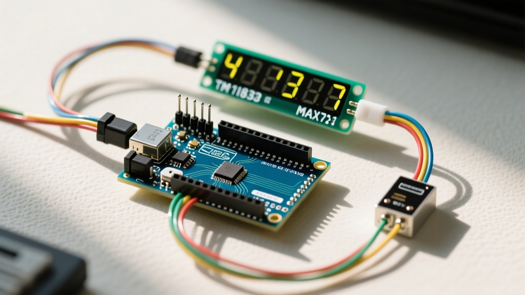
For this integration, we will use the widely available AM2302/DHT22 temperature and humidity sensor alongside an FC-113 TM1637 display module. The DHT22 is favored over the cheaper DHT11 due to its wider operating range (-40°C to 80°C) and 0.1°C resolution, which perfectly matches the decimal capabilities of a 4-digit display.
Pinout and Power Considerations
- DHT22 Sensor: VCC to 5V, GND to GND, Data Pin to Arduino Digital Pin 2. Critical: A 4.7kΩ pull-up resistor is mandatory between VCC and the Data Pin for reliable DHT signal integrity.
- TM1637 Display: VCC to 5V, GND to GND, CLK to Digital Pin 3, DIO to Digital Pin 4.
- Decoupling: Solder a 100nF (0.1µF) ceramic capacitor directly across the VCC and GND pins on the back of the TM1637 PCB. This suppresses high-frequency switching noise generated by the display driver, preventing phantom button presses if your project also includes tactile switches.
Non-Blocking Code Architecture for Sensor Polling
The DHT22 sensor is notoriously slow. It requires up to 250ms to complete a single read cycle, and the manufacturer strictly mandates a 2-second delay between consecutive polls to allow the internal thermistor to stabilize. If you use delay(2000) in your main loop, your entire microcontroller freezes. While the TM1637's internal RAM will keep the display lit during this freeze, any other peripherals (like PIR motion sensors or serial communication) will be completely unresponsive.
To solve this, we utilize a non-blocking timing architecture using the Arduino millis() function. This allows the main loop to spin continuously, checking if 2,000 milliseconds have elapsed since the last sensor read without halting execution.
Core Logic Flow
- Initialize the
TM1637DisplayandDHTlibraries insetup(). - Set the display brightness (0-7). Start at level 4 to reduce thermal load on the module's voltage regulator.
- In the
loop(), capture the currentmillis()timestamp. - Subtract the previous timestamp. If the delta is ≥ 2000ms, trigger the DHT read.
- Format the float temperature value into an integer array representing the segments, and push to the TM1637.
By structuring the code this way, the Arduino remains free to handle hardware interrupts from other sensors, ensuring your 4-digit display acts as a true real-time dashboard rather than a bottleneck.
Real-World Failure Modes and Troubleshooting
Even with a dedicated driver IC, field deployments of 7-segment sensor displays frequently encounter edge cases. Here is how to diagnose and resolve the most common issues:
- Ghosting and Dim Segments: If faint, incorrect numbers appear on unlit digits, your TM1637 CLK/DIO lines are suffering from signal reflection or lack of pull-up. While the TM1637 has internal pull-ups, adding external 10kΩ pull-up resistors to the 5V rail on the CLK and DIO lines eliminates ghosting in environments with high electromagnetic interference (EMI), such as near relay modules or AC motors.
- Microcontroller Brownouts (MAX7219 Specific): If you opt for the MAX7219 to drive larger, high-brightness displays, be aware of the current draw. Lighting all 32 segments plus decimal points at maximum intensity can pull over 300mA. The Arduino Uno's onboard 5V linear regulator (usually an NCP1117) will overheat and drop the voltage below 4.5V, causing the ATmega328P to endlessly reset. Solution: Bypass the Arduino's 5V pin entirely. Power the MAX7219 VCC directly from an external 5V 1A buck converter, tying the grounds together.
- Decimal Point Misalignment: When displaying sensor data like '23.4°C', the decimal point must be placed correctly. On the TM1637, the decimal point is not a separate pin; it is the 8th bit of the segment byte. You must bitwise OR (
|) the segment data with0x80to activate the decimal point on a specific digit without altering the numerical segments.
Advanced Integration: Daisy-Chaining for Multi-Sensor Arrays
If your project requires monitoring multiple sensors simultaneously—for example, a greenhouse setup tracking Zone 1 and Zone 2 temperatures—the TM1637 falls short because it lacks native daisy-chaining capabilities. You would need to consume two additional GPIO pins for every extra display.
This is where the MAX7219 SPI driver proves its worth. The MAX7219 features a DOUT (Data Out) pin that allows you to chain multiple 4-digit displays in series using only three Arduino pins (DIN, CLK, CS). The data is shifted through the displays like a shift register. By utilizing the LedControl library, you can address display 0 for your DHT22 readout and display 1 for an HC-SR04 ultrasonic water tank level sensor, updating them independently via SPI commands without increasing your wiring complexity.
Summary
Successfully integrating an Arduino 4 digit 7 segment display into a sensor project hinges on respecting the hardware's electrical limits and the microcontroller's timing constraints. By selecting the correct driver IC (TM1637 for low-pin-count simplicity, MAX7219 for scalable SPI dashboards), implementing proper decoupling capacitors, and strictly utilizing non-blocking millis() polling for your sensors, you will build a robust, flicker-free telemetry system capable of surviving real-world deployment.