
Beyond the Tutorial: Why Datasheets Matter for Motion Sensing
Most beginner guides treating an Arduino with motion sensor setups reduce the process to three wires: VCC, GND, and OUT. While this might blink an LED, it inevitably leads to field failures in 2026's demanding edge-IoT environments. Phantom triggers, rapid battery depletion, and logic-level frying are the hallmarks of developers who skip the datasheet. To build robust security nodes, automated lighting, or wildlife cameras, we must deconstruct the silicon driving these cheap but capable modules.
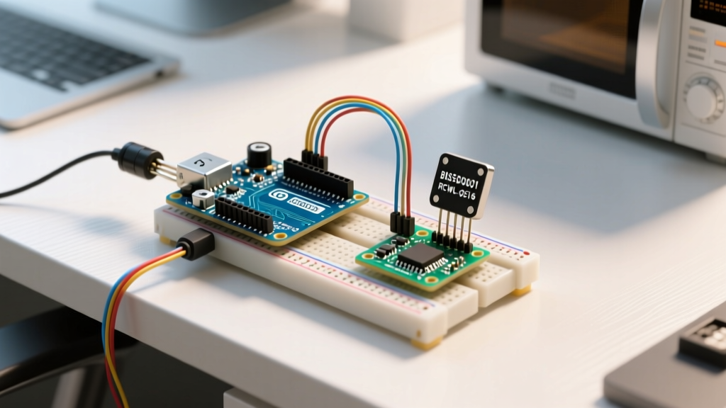
In this datasheet explainer, we dissect the two most ubiquitous motion sensors in the maker ecosystem: the HC-SR501 (driven by the BISS0001 PIR controller chip) and the RCWL-0516 (a 3.18 GHz microwave Doppler radar). By understanding the underlying physics and timing formulas, you can eliminate false positives and optimize your microcontroller's sleep states.
Deconstructing the HC-SR501: The BISS0001 Chip Explained
The HC-SR501 is essentially a breakout board for the BISS0001 PIR motion detector IC, paired with a Fresnel lens array. According to Adafruit's comprehensive PIR guide, the sensor detects changes in infrared radiation, not absolute heat. This distinction is critical for placement.
Timing Resistors and the Tx Formula
The BISS0001 datasheet defines two critical timing phases controlled by external resistors and capacitors on the HC-SR501 board:
- Output Delay Time (Tx): How long the OUT pin stays HIGH after motion ceases. Controlled by Rt2 and Ct2. The formula is
Tx ≈ 24,000 × Rt2 × Ct2. With the stock 1MΩ resistor and 0.01µF capacitor, Tx is roughly 2.5 seconds. Swapping Rt2 for a 10kΩ potentiometer allows precise tuning from milliseconds to seconds. - Block Time (Ti): The mandatory 'blind' period after Tx expires where the sensor ignores all IR changes. Controlled by Rt1 and Ct1.
Ti ≈ 24,000 × Rt1 × Ct1. Stock values yield roughly 1.2 seconds of block time.
Trigger Modes: Retriggerable (H) vs. Non-Retriggerable (L)
The physical jumper on the HC-SR501 dictates how the BISS0001 handles continuous motion:
H Mode (Retriggerable): Every new detection resets the Tx timer. If a person stands in front of the sensor waving, the output stays HIGH continuously. Ideal for room lighting.
L Mode (Non-Retriggerable): Once triggered, the sensor goes blind for the Ti block time, regardless of ongoing motion. Ideal for counting discrete entries through a doorway.
The 30-Second Initialization Blind Spot
A common failure mode in DIY security systems is triggering an alarm immediately upon power-up. The BISS0001 datasheet explicitly mandates a 30-second initialization period. During this time, the internal op-amps stabilize and the chip maps the baseline ambient IR environment. Your Arduino code must include a blocking delay or a state-machine wait during boot to ignore triggers within this window.
Microwave Radar Alternative: RCWL-0516 Doppler Specs
While PIR requires line-of-sight and detects surface heat differentials, the RCWL-0516 utilizes microwave Doppler shift at 3.18 GHz. It emits electromagnetic waves and measures the frequency shift of the bouncing signal. As noted in Texas Instruments' motion sensing portfolio overview, radar-based sensing provides superior penetration through non-metallic materials, but introduces unique edge cases.
The 'Through-Wall' Failure Mode
Because 3.18 GHz microwaves easily penetrate drywall, plastic, and thin wood, the RCWL-0516 will trigger if a person walks in the next room. If you are building an Arduino-based intruder alarm for a specific room, you must shield the back of the sensor with copper tape or aluminum foil connected to the module's GND plane to create a directional Faraday cage.
Comparative Matrix: PIR vs. Microwave Radar
| Specification | HC-SR501 (PIR / BISS0001) | RCWL-0516 (Microwave Radar) |
|---|---|---|
| Detection Method | Passive Infrared (Heat Differential) | Active Doppler Radar (3.18 GHz) |
| Operating Voltage | 4.5V to 20V (5V recommended) | 2.8V to 3.6V (3.3V native) |
| Quiescent Current | < 50 µA | ~ 3 mA (Active RF emission) |
| Line of Sight Required? | Yes (Blocked by glass/plastic) | No (Penetrates thin walls) |
| Best Use Case (2026) | Battery-powered sleep nodes, room occupancy | Hidden sensors, presence through enclosures |
Logic Level Translation: Protecting 3.3V Microcontrollers
In modern deployments, developers frequently pair an Arduino with motion sensor modules using 3.3V logic boards like the Arduino Nano 33 IoT, ESP32-S3, or Raspberry Pi Pico. This is where hardware destruction occurs.
The HC-SR501, when powered by 5V, outputs roughly 3.5V to 4V on its OUT pin. While a 5V ATmega328P (Arduino Uno) reads this safely, feeding 4V into a 3.3V GPIO pin on an ESP32 will degrade the silicon over time and eventually fry the pin. Actionable Fix: Use a bidirectional logic level shifter (like the BSS138 MOSFET-based modules) or a simple voltage divider (10kΩ and 20kΩ resistors) to step the HC-SR501's output down to a safe 3.3V.
Conversely, the RCWL-0516 natively operates at 3.3V and outputs 3.3V logic, making it inherently safe for modern low-voltage MCUs without extra components.
Interrupt Architecture vs. Polling Loops
Using a while(1) loop with digitalRead() to check a motion sensor is a relic of the past. For any battery-operated Arduino project in 2026, you must utilize hardware interrupts to allow the microcontroller to enter deep sleep.
According to Arduino's official attachInterrupt() documentation, you should map the sensor's OUT pin to an interrupt-capable pin (e.g., Pin 2 or 3 on an Uno, or specific RTC_GPIO pins on an ESP32).
Implementation Strategy
- Hardware: Connect the sensor OUT pin to an interrupt-capable GPIO.
- Software: Use
attachInterrupt(digitalPinToInterrupt(sensorPin), wakeUp, RISING). - Sleep State: Put the MCU into
SLEEP_MODE_PWR_DOWN(AVR) oresp_deep_sleep_start()(ESP32). - Debounce: Motion sensors can exhibit micro-bounces on the trailing edge. Implement a software debounce in the ISR (Interrupt Service Routine) using
millis()to ensure the wake-up event is genuine.
RF Interference and False Positives
When integrating an Arduino with motion sensor arrays alongside Wi-Fi or Bluetooth modules (like the HC-05 or ESP8266), RF interference becomes a major variable. The HC-SR501's high-impedance analog front-end is notoriously susceptible to RF noise. If your Wi-Fi antenna is within 5cm of the PIR sensor, every data packet transmission can induce a voltage spike in the BISS0001's op-amp, registering as a false motion trigger.
Mitigation Protocol: Maintain a minimum 10cm physical separation between RF antennas and the PIR Fresnel lens. Additionally, solder a 104 (0.1µF) ceramic decoupling capacitor directly across the VCC and GND pins on the HC-SR501 PCB to filter high-frequency power rail noise generated by Wi-Fi transmission bursts.
Summary: Designing for the Edge
Successfully deploying an Arduino with motion sensor peripherals requires moving beyond basic wiring diagrams. By respecting the BISS0001's timing formulas, managing the 30-second initialization blind spot, shielding microwave radar from unintended penetration, and strictly adhering to 3.3V logic thresholds, you transition from a hobbyist to an embedded systems engineer. Read the datasheet, design for the edge cases, and your 2026 IoT deployments will operate flawlessly in the field.