
The Multi-Peripheral Power Bottleneck
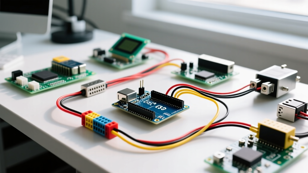
Integrating an arduino relay module into a complex sensor network is a rite of passage for DIY electronics enthusiasts. Whether you are building an automated 2026 hydroponic dosing system or a multi-zone incubator, you will eventually need to switch high-current loads. However, dropping a standard 4-channel or 8-channel relay board into a setup already running I2C OLED displays, SPI SD cards, and precision analog sensors frequently leads to catastrophic system instability. The ATmega328P microcontroller resets, I2C buses lock up, and analog readings turn to noise.
The root cause is almost always a combination of power rail collapse and electromagnetic interference (EMI). To build a robust multi-peripheral setup, you must treat the relay module not just as a digital output, but as a heavy inductive load that requires strict power isolation and noise mitigation.
Peripheral Current Draw Matrix
Before wiring, you must audit your power budget. A standard 4-channel module using the ubiquitous Songle SRD-05VDC-SL-C relays (typically priced between $7 and $12 on Amazon or AliExpress) draws roughly 71mA per coil. When all four channels engage simultaneously, the module demands over 280mA just for the coils, plus current for the optocoupler LEDs.
| Component | Interface | Typical Draw | Peak Draw |
|---|---|---|---|
| SSD1306 128x64 OLED | I2C | 20mA | 35mA |
| DS18B20 Temp Sensor (x4) | 1-Wire | 6mA | 12mA |
| HX711 Load Cell Amp | Digital | 1.5mA | 3mA |
| 4-Ch Relay Module (Coils) | 5V Rail | 210mA | 284mA |
| Arduino Uno R3 (Base) | MCU | 45mA | 50mA |
According to the Arduino Uno R3 official documentation, the onboard 5V linear regulator can theoretically supply up to 800mA, but thermal throttling severely limits this when powered via the barrel jack. If powered via USB, you are constrained by the host port's 500mA limit. Engaging four relays while polling sensors will easily trigger a brownout detector (BOD) reset.
The JD-VCC Jumper: Your Isolation Lifeline
Most commercial Arduino relay modules feature a PC817 optocoupler and a three-pin header labeled VCC | JD-VCC | GND with a plastic jumper cap connecting VCC and JD-VCC. For multi-peripheral setups, you must remove this jumper.
Step-by-Step Galvanic Isolation Wiring
- Remove the Jumper: Pull the plastic cap bridging VCC and JD-VCC.
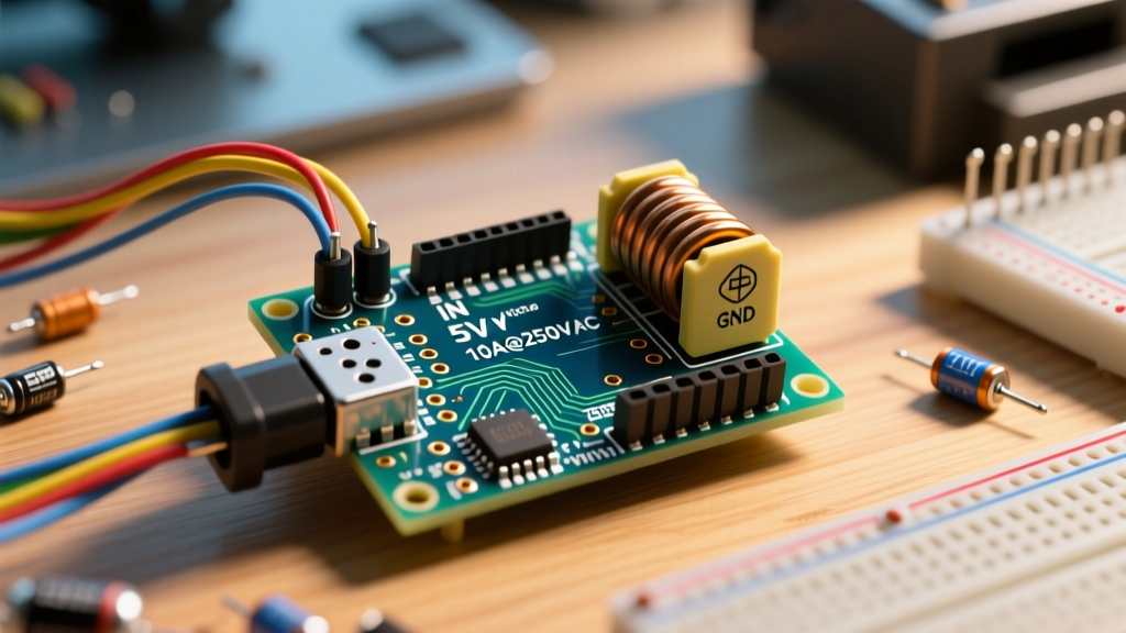
- Power the Coils (JD-VCC): Connect an external 5V power supply (such as an LM2596 buck converter module set to 5.0V, costing ~$2) to the JD-VCC and GND pins. This external supply will handle the heavy 284mA coil current.
- Power the Logic (VCC): Connect the Arduino's 5V (or 3.3V for ESP32 users) to the VCC pin. This powers only the low-current infrared LEDs inside the optocouplers (approx. 5mA per channel).
- Common Ground: Connect the Arduino GND to the external power supply GND to establish a common logic reference.
By splitting the power rails, the massive current spikes required to energize the relay coils no longer sag the Arduino's 5V logic rail. This single hardware modification eliminates 90% of the random microcontroller resets and I2C display freezes seen in complex builds.
GPIO Allocation and Signal Integrity
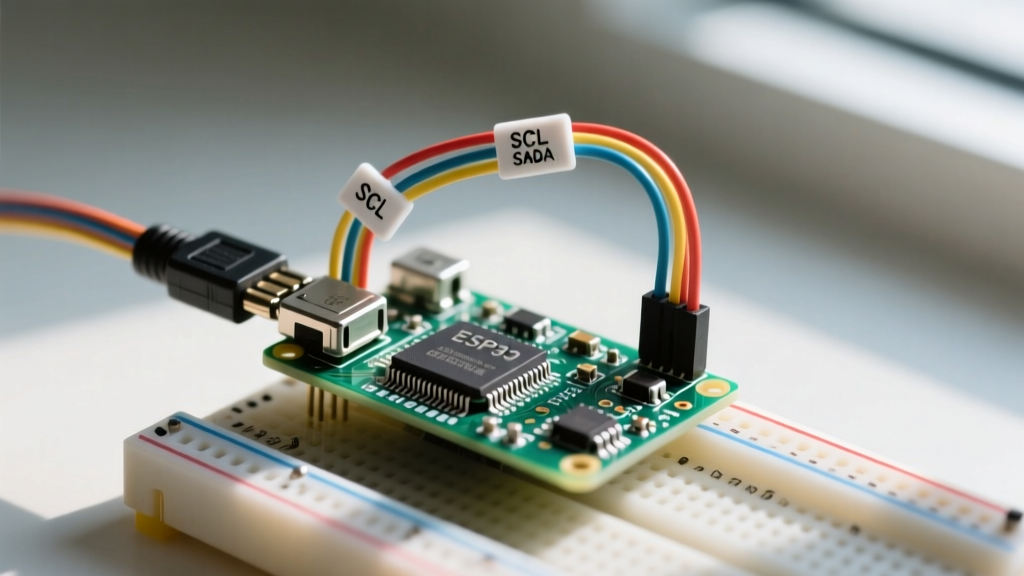
When mapping relay control pins, avoid clustering them near high-speed communication buses. Relay switching generates transient noise on the ground plane. If your relay control wires are routed parallel to your I2C SDA/SCL lines, the capacitive coupling can corrupt data packets.
- Reserve Pins 2 & 3: Keep these free for hardware interrupts (useful for flow sensors or rotary encoders).
- Avoid SPI Pins (10, 11, 12, 13): If you are logging data to an SD card, keep relay pins far from the SPI bus to prevent clock line interference.
- Use Analog Pins as Digital: Pins A0-A5 can be safely used as digital outputs (D14-D19) for relay control, keeping your digital cluster organized.
Mitigating EMI and Inductive Kickback
While the optocoupler protects the Arduino from DC back-EMF generated by the relay coil itself, it does nothing to protect your sensors from the EMI generated by the load being switched. As detailed in SparkFun's comprehensive relay tutorial, opening the contacts on an inductive load (like a solenoid valve, AC pump, or transformer) causes the collapsing magnetic field to arc across the contacts, broadcasting a massive broadband RF spike.
Expert Insight: If your HX711 load cell readings suddenly spike or your DS18B20 temperature sensors throw CRC errors exactly when a relay clicks off, you are experiencing inductive kickback EMI. The relay module's built-in 1N4007 flyback diode only protects the coil circuit, not the switched load.
Load-Side Protection Strategies
To maintain signal integrity across your peripheral network, you must implement load-side suppression:
- DC Inductive Loads (Solenoids, Pumps): Install a 1N4007 flyback diode in reverse bias directly across the load terminals. As Adafruit's guide on inductive kickback explains, this provides a safe recirculation path for the collapsing magnetic field.
- AC Inductive Loads (Motors, Compressors): Diodes do not work on AC. Instead, wire an RC snubber network (typically a 47-ohm carbon composition resistor in series with a 0.1µF X2-rated safety capacitor) across the relay's Normally Open (NO) and Common (COM) terminals.
- Twisted Pair Routing: Run your I2C and SPI sensor cables as twisted pairs, and physically separate them from AC load wiring by at least 2 inches to minimize inductive coupling.
Non-Blocking Code Architecture
In a multi-peripheral setup, your microcontroller must continuously poll sensors, update displays, and log data. Using the delay() function to time relay states will blind your system to sensor inputs during the delay window.
Always implement a state-machine approach using millis(). This allows the relay to remain engaged for a precise duration (e.g., a 3-second water valve pulse) while the main loop continues to read the DHT22 humidity sensor and refresh the OLED display at 30FPS. Furthermore, wrap your relay toggling logic in zero-crossing detection routines if you are switching heavy AC loads, to further minimize EMI generation at the exact moment of contact closure.
Troubleshooting Multi-Peripheral Failures
| Symptom | Root Cause | Hardware/Software Solution |
|---|---|---|
| Arduino resets when 3rd relay engages | 5V rail brownout due to coil current draw | Implement JD-VCC isolation with external 5V buck converter |
| I2C OLED freezes or shows garbage | EMI corrupting SDA/SCL lines or I2C address clash | Add 4.7k pull-up resistors to I2C lines; route away from relay coils |
| Relay clicks but load doesn't power | Exceeded contact rating (e.g., 10A limit) causing welded contacts or high resistance | Use a logic-level MOSFET (IRLZ44N) or contactor for loads >8A |
| Analog sensor readings spike on relay off | Inductive kickback from the switched load | Install flyback diode (DC) or RC snubber (AC) across the load |
Final Thoughts on System Reliability
Successfully integrating an arduino relay module into a dense multi-peripheral environment requires moving beyond basic breadboard tutorials. By budgeting your 5V current draw, leveraging the JD-VCC optocoupler isolation, and aggressively suppressing inductive EMI at the load, you transform a fragile prototype into a robust, deployment-ready controller. Whether you are managing a 2026 smart-home HVAC retrofit or an off-grid agricultural monitor, these electrical engineering fundamentals ensure your sensors stay accurate and your microcontroller stays online.