
The Evolution of Arduino 7 Seg Display Interfacing
When building digital clocks, scoreboards, or telemetry dashboards, the humble seven-segment display remains a staple in electronics. However, the way we interface an Arduino 7 seg display setup has evolved dramatically. In the early days of the Arduino Uno R3, makers relied on brute-force software multiplexing to drive raw LED digits. Today, with the rise of 32-bit microcontrollers like the Arduino Uno R4 Minima and the ESP32, dedicated driver ICs have largely taken over, freeing up CPU cycles for RTOS tasks and wireless communication.
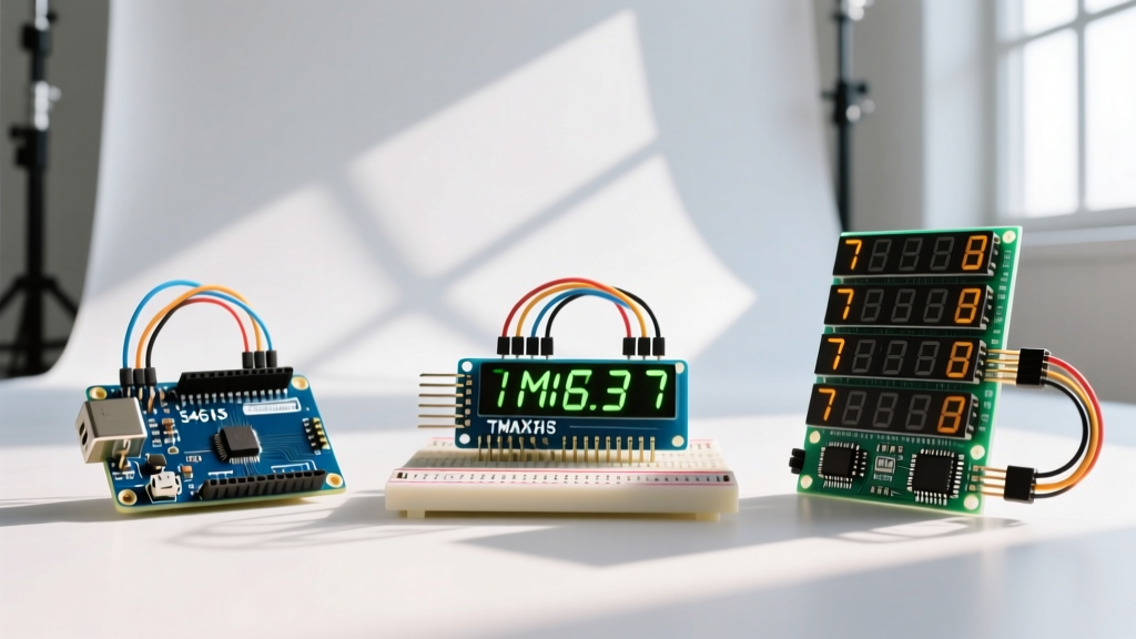
If you are designing a new project in 2026, choosing the right display architecture is critical. This component comparison breaks down the three dominant approaches: raw common-cathode LED matrices (like the 5461AS), the ubiquitous TM1637 2-wire modules, and the heavyweight MAX7219 SPI-driven displays. We will examine wiring complexity, CPU overhead, real-world pricing, and the specific failure modes that plague each approach.
Head-to-Head: Component Comparison Matrix
Before diving into the schematic-level details, here is a high-level comparison of the three primary architectures for driving an Arduino 7 seg display.
| Feature | Raw 5461AS (4-Digit) | TM1637 Module (4-Digit) | MAX7219 Module (8-Digit) |
|---|---|---|---|
| Interface Protocol | Direct GPIO / Shift Registers | Custom 2-Wire Serial | Hardware SPI |
| MCU Pins Required | 12 (w/o shift registers) | 2 (CLK, DIO) | 3 (DIN, CS, CLK) |
| Avg. Module Price (2026) | $0.45 - $0.60 | $1.10 - $1.50 | $2.20 - $3.00 |
| CPU Overhead | High (Requires Timer Interrupts) | Low (Blocking I2C-like) | Minimal (Hardware SPI DMA) |
| Brightness Control | Software PWM | 8-Level Hardware | 16-Level Hardware |
| Daisy-Chaining | Not Practical | No (Addressless) | Yes (Up to 8 modules) |
Deep Dive: Raw 4-Digit Common Cathode (5461AS)
The raw 4-digit display, commonly sold under the part number 5461AS or 5161BS (common anode), is the most fundamental Arduino 7 seg display option. It contains 28 internal LEDs (4 digits × 7 segments + 4 decimal points). In a common-cathode configuration, the cathodes of each digit are tied together to four separate ground pins, while the anodes for each segment (A-G, DP) are tied across the digits.
Wiring and Current Calculations
Driving a raw display requires an understanding of seven-segment display architecture and forward voltage drops. A standard red 5461AS has a forward voltage ($V_f$) of approximately 2.0V and a recommended forward current ($I_f$) of 15mA per segment.
- Current Limiting Resistors: Assuming a 5V Arduino VCC, the resistor calculation is $R = (5V - 2.0V) / 0.015A = 200\Omega$. You must use eight $220\Omega$ resistors on the segment lines.
- Transistor Switching: An Arduino GPIO pin can typically source/sink up to 20mA (absolute max 40mA). A single digit with all 8 segments lit draws $8 \times 15mA = 120mA$. This will destroy a microcontroller pin. You must use NPN transistors (like the 2N3904 or BC547) to sink the common cathode pins, triggered via a $1k\Omega$ base resistor.
The Multiplexing Burden
To display "1234", the Arduino must cycle through each digit rapidly, relying on Persistence of Vision (POV). To achieve a flicker-free 60Hz refresh rate across 4 digits, your timer interrupt must fire at 240Hz (every 4.16ms). While the 74HC595 shift register can reduce GPIO usage, the CPU overhead for software multiplexing remains high, making this approach poor for projects requiring heavy background processing.
Deep Dive: TM1637 4-Digit Module (The I2C-Like Favorite)
The TM1637 module is the undisputed king of quick-prototype Arduino 7 seg display integrations. Priced around $1.20, it features a 4-digit display pre-mounted on a PCB with the Titan Micro TM1637 LED driver IC. It requires only two data wires: CLK and DIO.
Protocol Quirks and Library Usage
Despite looking like I2C, the TM1637 protocol is proprietary. It uses a Start condition (DIO goes low while CLK is high) and an Acknowledge pulse, but it lacks device addressing. This means you cannot put multiple TM1637 modules on the same two bus wires; each module requires its own dedicated CLK and DIO pins.
The most reliable library in the 2026 ecosystem is the TM1637Display library by Avishay Orpaz. It handles the bit-banging timing automatically. Because the TM1637 contains internal SRAM and handles multiplexing in hardware, your Arduino only needs to send data when the display updates, dropping CPU overhead to near zero.
Deep Dive: MAX7219 8-Digit Module (The Heavyweight)
For industrial telemetry, large clocks, or complex计分 boards, the MAX7219 is the professional choice. Originally designed by Maxim Integrated (now Analog Devices), this IC drives up to 8 digits (or a 64-LED matrix) via a standard SPI interface. You can review the exact timing diagrams in the Texas Instruments MAX7219 Datasheet.
Hardware SPI and Daisy Chaining
Unlike the TM1637, the MAX7219 uses true SPI (Mode 0, CPOL=0, CPHA=0). As detailed in the Arduino SPI Communication Guide, hardware SPI allows the microcontroller to offload data shifting to a dedicated peripheral, often utilizing DMA (Direct Memory Access) on modern boards like the Arduino GIGA R1 or Portenta H7.
The true power of the MAX7219 is daisy-chaining. The IC features a DOUT pin that cascades data to the next module's DIN. You can wire eight 8-digit modules in series (64 digits total) using only the same 3 MCU pins (DIN, CS, CLK). The LedControl library handles the BCD (Binary Coded Decimal) decoding and intensity registers seamlessly.
Real-World Failure Modes & Edge Cases
Theory is clean; workbenches are messy. Here are the specific edge cases you will encounter when wiring an Arduino 7 seg display setup.
Expert Warning: The MAX7219 Brownout
An 8-digit MAX7219 module with all segments lit at maximum current (configured via the $R_{set}$ resistor, usually 10kΩ for 20mA/segment) can draw peaks exceeding 1A. If you power the module directly from the Arduino Uno's 5V USB rail, you will trip the host PC's USB overcurrent protection or the Arduino's polyfuse. Always use an external 5V 2A buck converter for MAX7219 arrays, tying the grounds together.
1. Ghosting on Raw Multiplexed Displays
Symptom: Faint, incorrect numbers appear on adjacent digits.
Cause: GPIO pins are not cleared before switching the common cathode transistor. The previous digit's segment data bleeds into the new digit for a few microseconds.
Fix: Implement a strict sequence in your interrupt service routine (ISR): 1) Turn off all segment pins. 2) Disable the current cathode transistor. 3) Enable the next cathode transistor. 4) Write the new segment data.
2. TM1637 Signal Degradation on Long Wires
Symptom: Display flickers or shows random characters when wires exceed 30cm.
Cause: The TM1637 lacks the robust push-pull drivers of true I2C. Stray capacitance on long dupont wires rounds off the square wave edges.
Fix: Solder $4.7k\Omega$ pull-up resistors to the CLK and DIO lines at the display end, or reduce the bit-bang delay in the library source code if using a 3.3V ESP32.
3. MAX7219 SPI Glitches
Symptom: Display updates randomly or freezes.
Cause: Voltage spikes on the 5V rail corrupting the SPI clock edge.
Fix: Solder a $10\mu F$ electrolytic and a $0.1\mu F$ ceramic decoupling capacitor directly across the VCC and GND header pins of the MAX7219 module. Do not rely on the PCB's factory routing for high-frequency decoupling.
Expert Verdict: Which Arduino 7 Seg Display Should You Choose?
- Choose Raw 5461AS if you are designing a custom PCB, need to minimize BOM costs at scale (under $0.50/unit), or are building a retro-nixie style clock where custom multiplexing is part of the learning experience.
- Choose TM1637 for 90% of hobbyist projects. It is the ultimate balance of low cost ($1.20), minimal wiring (2 pins), and ease of use for simple 4-digit readouts like temperature sensors or timers.
- Choose MAX7219 for mission-critical dashboards, large-scale daisy-chained scoreboards, or projects where CPU cycles are strictly reserved for PID control loops or high-speed data logging.
Frequently Asked Questions (FAQ)
Can I run a 5V Arduino 7 seg display module on a 3.3V ESP32?
The TM1637 and MAX7217/7219 logic inputs generally recognize 3.3V as a HIGH signal, but the LED VCC still requires 5V to achieve adequate brightness. For MAX7219, ensure you use a logic level shifter on the DIN and CLK lines if the ESP32 struggles to hit the $V_{IH}$ threshold of the IC.
Why do some TM1637 modules have a colon that won't light up?
On many cheap 4-digit TM1637 clones, the center colon is hardwired to the second digit's decimal point (DP) pin. To light the colon, you must send the DP bit for the second digit in your data array, rather than looking for a dedicated colon command.
How do I prevent burn-in on raw LED displays?
While LEDs do not suffer from phosphor burn-in like OLEDs, running a raw display at 20mA continuously for years will cause lumen depreciation (dimming). Use the MAX7219 or TM1637 hardware intensity registers to drop the current to 5mA for indoor use, which extends the display lifespan almost indefinitely.