
The Evolution of Arduino Sound Sensor Integration
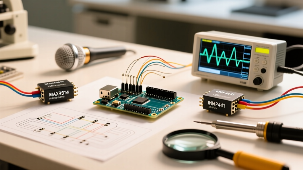
When makers first search for an Arduino sound sensor, they are usually met with the KY-038 or LM393 analog modules. While these $1.50 boards are fine for detecting a loud hand clap, they fail miserably at capturing actual audio waveforms, voice commands, or complex acoustic events. In 2026, professional IoT and robotics projects demand higher fidelity. This guide bypasses the toy-grade sensors and dives deep into integrating the MAX9814 analog microphone amplifier and the INMP441 I2S digital MEMS microphone into your microcontroller ecosystem.
Hardware Matrix: Choosing the Right Acoustic Transducer
Selecting the correct sensor depends entirely on your signal processing requirements. Are you triggering a relay on a loud noise, or streaming FFT data for voice recognition?
| Module | Interface | Best Use Case | Typical Cost (2026) | MCU Compatibility |
|---|---|---|---|---|
| KY-038 (LM393) | Digital (Threshold) | Clap switches, basic noise alarms | $1.50 - $2.00 | Any (Uno, Nano, ESP32) |
| MAX9814 | Analog (Envelope/Audio) | Audio level metering, glass-break detection | $6.00 - $8.50 | AVR Arduinos, ESP32 (Requires ADC) |
| INMP441 | I2S Digital (24-bit) | Voice recognition, FFT, audio streaming | $4.00 - $5.50 | ESP32, Nano 33 BLE, Portenta (No I2S on Uno) |
Deep Dive 1: MAX9814 Analog Envelope Detection
The MAX9814 is an electret microphone amplifier featuring a built-in Auto Gain Control (AGC) and low-noise bias. The AGC is critical: it prevents loud sounds from clipping the amplifier while boosting quiet sounds, maintaining a consistent output envelope.
Wiring the MAX9814 to an Arduino Uno R4
- VCC: Connect to 5V (or 3.3V depending on your MCU's ADC reference).
- GND: Connect to a common ground.
- OUT: Connect to Analog Pin A0.
- AGC Attack/Release: By default, the attack time is 2ms and release is 100ms. You can modify this by adding a capacitor between the CT pin and GND if your application requires slower acoustic decay tracking.
Expert Insight: The MAX9814 output is biased at VCC/2. On a 5V Arduino Uno, the resting analogRead() value will hover around 512. Do not attempt to read raw audio waves at 44.1kHz on a standard 16MHz AVR Arduino; the ADC cannot sample fast enough without severe aliasing. Instead, read the envelope (overall volume level) at 50Hz - 100Hz.
Envelope Follower Code Snippet
This code calculates the peak-to-peak amplitude over a 50ms window, perfect for triggering events based on volume spikes rather than specific frequencies.
const int micPin = A0;
const int sampleWindow = 50; // Sample window width in mS (50 mS = 20Hz)
unsigned int sample;

void setup() {
  Serial.begin(115200);
  analogReference(DEFAULT); // Ensure 5V reference on Uno
}

void loop() {
  unsigned long startMillis = millis();
  unsigned int peakToPeak = 0;
  unsigned int signalMax = 0;
  unsigned int signalMin = 1024;

  while (millis() - startMillis < sampleWindow) {
    sample = analogRead(micPin);
    if (sample < 1024) { // Toss out spurious readings
      if (sample > signalMax) signalMax = sample;
      else if (sample < signalMin) signalMin = sample;
    }
  }
  peakToPeak = signalMax - signalMin;
  // Map to a 0-100 scale for easy thresholding
  int dbScaled = map(peakToPeak, 0, 900, 0, 100);
  Serial.println(dbScaled);
  delay(10);
}
Deep Dive 2: INMP441 I2S Digital Audio Capture
If your project requires actual audio data (e.g., feeding an ESP32 into a cloud speech-to-text API or running local TensorFlow Lite Micro keyword spotting), analog sensors are insufficient due to ADC quantization noise. The INMP441 is an omnidirectional MEMS microphone with a built-in I2S interface.
The I2S Bottleneck on Classic Arduinos
A critical failure mode for beginners is attempting to wire an INMP441 to an Arduino Uno or Mega. Classic AVR Arduinos lack a hardware I2S peripheral. Bit-banging I2S at 44.1kHz on a 16MHz ATmega328P will result in dropped clock cycles and corrupted audio. You must use an Arduino board with native I2S or PDM support, such as the Arduino Nano 33 BLE Sense or an ESP32 programmed via the Arduino IDE. For comprehensive bus timing and pull-up requirements, consult the Espressif I2S API Documentation.
INMP441 to ESP32 Pinout Matrix
| INMP441 Pin | ESP32 Pin | Function & Notes |
|---|---|---|
| VDD | 3.3V | CRITICAL: Do not connect to 5V. The INMP441 operates strictly at 1.8V to 3.3V. 5V will instantly destroy the MEMS element. |
| GND | GND | Common ground. |
| L/R | GND or VDD | Channel Select. Tie to GND for Left Channel, Tie to VDD for Right Channel. |
| WS | GPIO 25 | Word Select / Left-Right Clock (LRCLK). |
| SCK | GPIO 26 | Serial Clock (BCLK). Typically 64x the sample rate. |
| SD | GPIO 22 | Serial Data (DOUT). Connect to MCU's I2S Data In pin. |
For authoritative implementation details on I2S MEMS microphones, refer to the Adafruit I2S MEMS Breakout Guide, which details the hardware nuances essential for stable I2S bus communication.
Advanced Troubleshooting & Acoustic Failure Modes
Even with the right hardware, environmental and electrical factors can ruin your sensor integration. Here is how to diagnose the most common issues:
1. The 60Hz Ground Loop Hum
Symptom: Your MAX9814 FFT shows a massive spike at 60Hz (or 50Hz in Europe), drowning out voice frequencies.
Cause: Sharing a ground return path with high-current components like DC motors or relay coils.
Solution: Implement a star ground topology. Run a dedicated ground wire from the MAX9814 directly to the Arduino's GND pin, completely isolated from the motor driver's ground return. Additionally, place a 10µF tantalum and a 0.1µF ceramic capacitor in parallel across the sensor's VCC and GND pins to filter high-frequency switching noise.
2. MEMS Microphone Saturation (Clipping)
Symptom: The INMP441 outputs flatlined maximum values when a loud noise occurs.
Cause: The INMP441 has an Acoustic Overload Point (AOP) of 116 dBA. If placed inside a sealed, poorly vented 3D-printed enclosure, acoustic resonance can artificially amplify internal SPL (Sound Pressure Level) past the AOP.
Solution: Ensure your enclosure has a properly tuned acoustic port (a small hole matching the MEMS sound port diameter, typically 1mm to 2mm). Never press the microphone's sound port directly against a flat surface.
3. ADC Non-Linearity on Analog Sensors
Symptom: The analogRead() values on the MAX9814 seem "jumpy" or non-linear at low volumes.
Cause: The internal ADC of the ATmega328P has a high input impedance requirement (ideally < 10kΩ). While the MAX9814 output impedance is low, long unshielded jumper wires act as antennas, picking up RF interference from nearby Wi-Fi routers or switching power supplies.
Solution: Use shielded twisted-pair cable for runs longer than 15cm. For high-precision analog audio capture, bypass the internal ADC entirely and use an external I2S ADC like the PCM1808.
Software Libraries for DSP and Keyword Spotting
Hardware is only half the battle. To process the data from your Arduino sound sensor, you need optimized libraries:
- arduinoFFT: Ideal for the MAX9814. Allows you to perform Fast Fourier Transforms on the analog envelope to detect specific frequency bands (e.g., isolating the 3kHz frequency of breaking glass).
- TensorFlow Lite Micro: The standard for INMP441 I2S audio. You can train a custom TinyML model on edge devices like the Arduino Nano 33 BLE Sense to recognize specific voice commands without cloud connectivity.
- ESP32-audioI2S: A robust library for streaming I2S data directly to web sockets or local SD cards for later analysis.
Summary: Architecting Your Audio Pipeline
Integrating an Arduino sound sensor is no longer limited to simple threshold triggers. By understanding the physical limitations of analog envelope detectors like the MAX9814 and the digital bus requirements of I2S MEMS sensors like the INMP441, you can design robust acoustic interfaces. Always match the sensor's output topology to your microcontroller's hardware peripherals, and pay meticulous attention to your grounding and acoustic enclosure design.
For further reading on digital audio signal processing on microcontrollers, the Arduino PDM Microphone Documentation provides excellent foundational knowledge on handling Pulse Density Modulation, a close relative to I2S used in modern onboard MCU microphones.