
The Case for Closed-Loop Thermal Management
Integrating dynamic cooling into DIY electronics, 3D printer enclosures, or home-lab server racks requires more than a simple thermal cutoff switch. True thermal management relies on proportional feedback. When executing an Arduino PWM fan control strategy, the goal is to modulate the fan's RPM in direct response to real-time temperature fluctuations, minimizing acoustic noise while preventing thermal throttling. In this advanced sensor integration tutorial, we will bypass the rudimentary on/off relay methods and build a closed-loop cooling system using a high-precision I2C temperature sensor and a logic-level MOSFET, tailored for the hardware landscape of 2026.
2026 Bill of Materials (BOM) & Component Selection
Selecting the right components is critical for avoiding the common pitfalls of PWM integration, such as acoustic whining and stall zones. Below is the optimized BOM for a high-reliability thermal control circuit.
| Component | Model / Specification | Approx. 2026 Price | Role in Circuit |
|---|---|---|---|
| Microcontroller | Arduino Uno R4 Minima | $27.50 | PWM generation & I2C sensor polling |
| Cooling Fan | Noctua NF-A12x25 PWM (12V) | $32.90 | Fluid dynamic bearing, 4-pin PWM input |
| Temp Sensor | Adafruit TMP117 I2C Breakout | $6.95 | High-accuracy (±0.1°C) thermal feedback |
| MOSFET | IRLZ44N (Logic-Level N-Channel) | $1.50 | Switching 12V/1.5A load via 5V logic |
| Protection | 1N4007 Flyback Diode | $0.10 | Inductive kickback suppression |
Hardware Architecture: The Logic-Level MOSFET Stage
While some modern 4-pin PWM fans feature an internal pull-up and can technically accept a 5V PWM signal directly on their blue control wire, relying on this is a poor engineering practice for 12V industrial or PC-grade fans. The Noctua NF-A12x25 PWM Specifications dictate a 5V/20mA logic signal, but driving the fan's power rail directly via PWM requires a robust switching mechanism.
Wiring the IRLZ44N and Flyback Protection
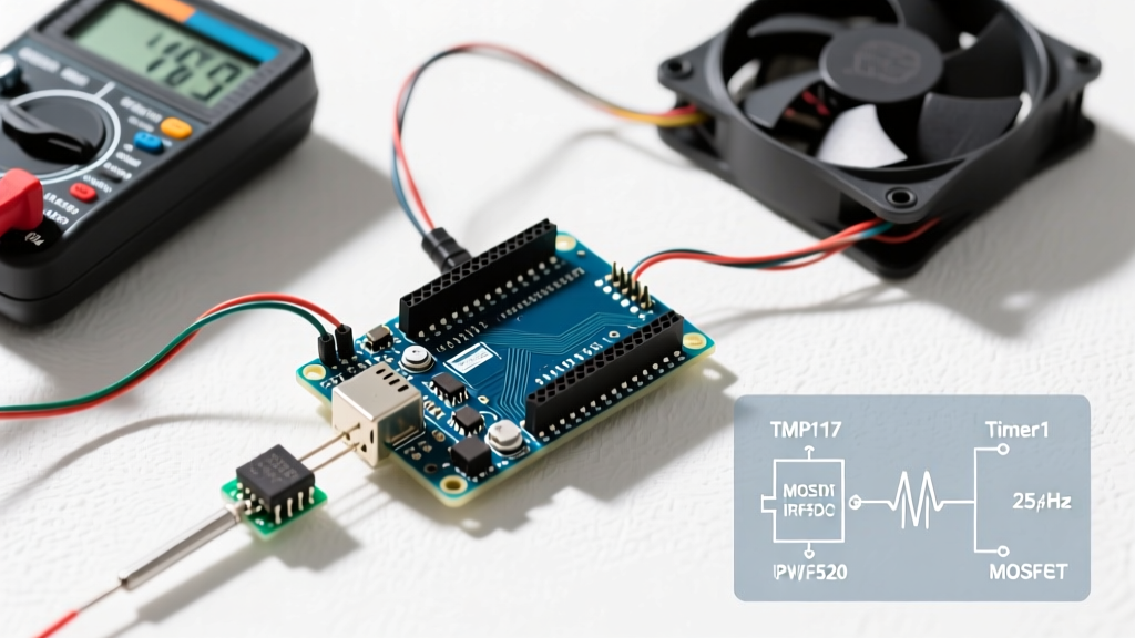
The Arduino Uno R4 Minima can only source 20mA per I/O pin. To switch a 12V fan drawing up to 1.5A, we use the IRLZ44N N-channel MOSFET. Unlike standard MOSFETs (like the IRF520) which require 10V+ at the gate to fully open, the IRLZ44N is a logic-level MOSFET. Its Vgs(th) threshold guarantees full Rds(on) conduction at the 5V output of the Arduino.
- Gate (G): Connect to Arduino Pin 9 via a 220Ω current-limiting resistor. Add a 10kΩ pull-down resistor between Gate and Ground to prevent erratic spinning during MCU boot-up.
- Drain (D): Connect to the negative (black) wire of the 12V fan.
- Source (S): Connect to the common Ground (shared between the 12V power supply and the Arduino).
- Flyback Diode: Place the 1N4007 diode in reverse bias across the fan's power terminals (cathode/stripe to 12V, anode to Drain). This is non-negotiable; when the MOSFET switches off, the fan's inductive motor coil generates a high-voltage spike that will instantly destroy the MOSFET without this diode.
Engineering Note: If you are utilizing a true 4-pin PWM fan, the fan's internal microcontroller handles the power switching. In this specific scenario, you keep the 12V and GND wires connected directly to the power supply, and only route the Arduino's Pin 9 PWM signal to the fan's blue PWM control wire. The MOSFET circuit described above is mandatory for 2-pin and 3-pin DC fans where you must chop the main power rail.
The 25kHz Frequency Dilemma (Timer1 Override)
The most frequent point of failure in DIY Arduino PWM fan control projects is acoustic whining. By default, the Arduino analogWrite() Reference documentation shows that Pins 5 and 6 operate at ~980Hz, while Pins 9, 10, 11, and 3 operate at ~490Hz.
PC and server fans are engineered to the Intel 4-Wire PWM specification, which mandates a 25kHz PWM frequency. Feeding a 490Hz signal into a fan's control circuit causes the internal capacitors and inductors to vibrate at an audible frequency, resulting in a maddening high-pitched whine. Furthermore, lower frequencies can cause erratic RPM readings on the fan's tachometer (yellow) wire.
Implementing TimerOne for 25kHz Output
To resolve this, we must override the default hardware timers using the TimerOne library. Pin 9 is tied to Timer1 on the ATmega/RA4M1 architecture. By setting the timer period to 40 microseconds (1 / 0.000040s = 25,000Hz), we achieve the exact 25kHz specification.
#include <TimerOne.h>

void setup() {
  Timer1.initialize(40); // 40us = 25kHz
  // Set initial fan speed to 0%
  Timer1.pwm(9, 0);
}
Instead of analogWrite(9, value), you will now use Timer1.pwm(9, duty_cycle), where the duty cycle ranges from 0 to 1023 (representing 0% to 100%).
Integrating the TMP117 I2C Sensor
Legacy tutorials often recommend the TMP36 analog sensor or the DHT22. In 2026, these are obsolete for precision thermal management. The TMP36 suffers from ADC noise and ±2°C variance, while the DHT22 is too slow (0.5Hz sampling rate). We use the Adafruit TMP117 Precision I2C Temperature Sensor Guide as our standard. The TMP117 offers ±0.1°C accuracy and a 16-bit resolution, communicating via I2C.
- VIN: 3.3V or 5V
- GND: Common Ground
- SCL: Arduino A5 (or SCL pin on R4 Minima)
- SDA: Arduino A4 (or SDA pin on R4 Minima)
Because the TMP117 uses I2C, it is immune to the analog noise generated by the switching MOSFET and the fan's motor, ensuring pristine temperature data.
Firmware Logic: Kickstart Routines & Proportional Bands
Mapping temperature directly to PWM duty cycle via a simple map() function ignores the physical realities of brushless DC motors. Most 120mm fans suffer from a "stall zone"—a voltage threshold below which the motor lacks the torque to overcome static friction, causing the fan to stutter or stop entirely.
The Kickstart Routine
To prevent stalling when transitioning from 0 RPM to a low target RPM, the firmware must implement a kickstart routine. Whenever the calculated target PWM duty cycle is greater than 0% but less than the fan's minimum operating threshold (typically 30% for high-static pressure fans), the code must briefly spike the PWM to 100% for 500 milliseconds.
void setFanSpeed(int targetPWM) {
  // targetPWM is scaled 0-1023
  int stallThreshold = 307; // ~30% duty cycle

  if (targetPWM > 0 && targetPWM < stallThreshold) {
    Timer1.pwm(9, 1023); // Kickstart at 100%
    delay(500);          // Hold for 500ms
  }
  Timer1.pwm(9, targetPWM);
}
Proportional Band Mapping
Rather than a single setpoint, implement a proportional band. Define a TEMP_MIN (e.g., 35°C) where the fan runs at a silent 20% duty cycle, and a TEMP_MAX (e.g., 55°C) where the fan runs at 100%. If the TMP117 reads below 35°C, the fan shuts off (0%). Between 35°C and 55°C, the map() function calculates the exact 10-bit PWM value required, creating a smooth, linear acoustic profile.
Real-World Failure Modes & Edge Cases
Even with perfect code, physical integration introduces edge cases. Be prepared to troubleshoot the following specific failure modes:
- Thermal Runaway via Sensor Placement: If the TMP117 is placed too close to the fan's exhaust, it will read the ambient room temperature rather than the heat sink's core temperature. Mount the sensor directly to the target thermal mass using thermal epoxy or Kapton tape, ensuring it is shielded from the fan's direct airflow.
- I2C Bus Lockups: The electromagnetic interference (EMI) generated by a 12V motor switching on and off can corrupt I2C packets, causing the Arduino to hang while waiting for a clock stretch. Always use 4.7kΩ pull-up resistors on the SDA and SCL lines, and keep the I2C wires under 30cm in length. Implement a hardware watchdog timer (WDT) in your firmware to reset the MCU if the I2C bus deadlocks.
- Tachometer Feedback Errors: If you are reading the fan's yellow tachometer wire to verify RPM, remember that the signal is an open-drain output. You must enable the Arduino's internal pull-up resistor (
pinMode(tachPin, INPUT_PULLUP)) and use hardware interrupts (attachInterrupt) to count the pulses accurately without blocking the main thermal control loop.
By combining the 25kHz Timer1 override, a logic-level MOSFET architecture, and the sub-degree accuracy of the TMP117, you elevate a basic DIY project into an enterprise-grade thermal management system capable of handling the rigorous demands of modern high-density electronics.