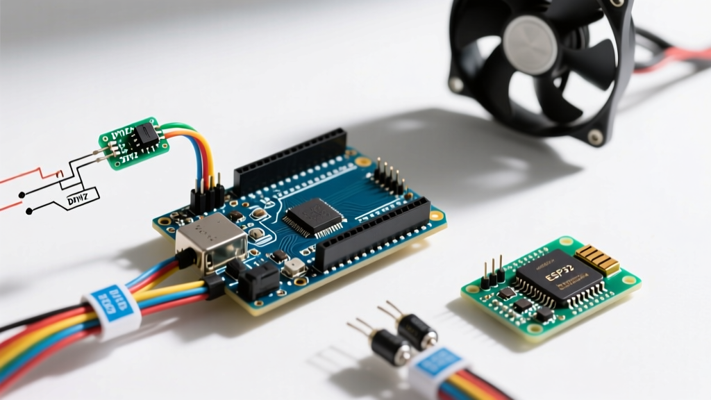

The Problem with Voltage-Based Fan Control
When integrating cooling systems into microcontroller projects, many beginners attempt to control 12V DC fans by simply varying the voltage using a linear regulator or a basic MOSFET in linear mode. This approach is fundamentally flawed. DC fans require a minimum "stall voltage" (typically around 7V to 9V) to keep the internal commutation circuitry running. Drop below this threshold, and the fan stalls, clicks, or fails to start entirely, potentially burning out its internal windings.
The professional solution is Pulse Width Modulation (PWM). By rapidly switching the full 12V supply on and off, or by using a dedicated 4-pin PWM control wire, the fan always receives the voltage it needs to operate its internal logic while the duty cycle dictates the rotational speed. In this tutorial, we will build a closed-loop Arduino PWM fan controller that dynamically adjusts cooling based on real-time temperature data from a DHT22 sensor.
Bill of Materials (BOM) and 2026 Pricing
For this build, we are prioritizing acoustic performance and reliability. While generic 3-pin fans require external MOSFET switching for the 12V rail, 4-pin PWM fans feature a dedicated logic-level PWM input pin, drastically simplifying the circuit.
| Component | Recommended Model | Approx. Cost (2026) | Notes |
|---|---|---|---|
| Microcontroller | Arduino Uno R3 or Nano | $6.50 (Clone) / $24.00 (Official) | Must have ATmega328P for Timer1 register access. |
| PWM Fan | Noctua NF-A12x25 PWM or Arctic P12 | $29.95 / $8.99 | 4-pin connector required for 25kHz logic control. |
| Temp Sensor | DHT22 / AM2302 | $4.99 | Superior accuracy (±0.5°C) over the cheaper DHT11. |
| Power Supply | 12V 2A DC Adapter | $8.50 | Provides ample headroom for fan startup current spikes. |
| Miscellaneous | 10kΩ Resistor, Jumper Wires | $1.00 | 10kΩ required as a pull-up for the DHT22 data line. |
Wiring the Arduino PWM Fan Circuit
The wiring topology for a 4-pin Intel-spec PWM fan is remarkably straightforward because the PWM control wire (Pin 4) is designed to accept 5V logic directly from microcontrollers like the Arduino Uno. You do not need a logic-level MOSFET or an optocoupler for the control signal.
Pinout Mapping Matrix
| Fan Wire Color | Standard Function | Arduino / PSU Connection |
|---|---|---|
| Black | Ground (GND) | Common Ground (PSU GND + Arduino GND) |
| Yellow | +12V Power | 12V PSU Positive Terminal |
| Green | Tachometer (Sense) | Arduino Pin 2 (Optional, for RPM feedback) |
| Blue | PWM Control | Arduino Pin 9 (Hardware PWM) |
CRITICAL GROUND LOOP WARNING: The 12V power supply's ground and the Arduino's ground must be tied together. Without a shared common ground, the 5V PWM signal from the Arduino will lack a reference voltage, causing the fan to run at 100% speed or behave erratically. According to SparkFun's PWM guide, a stable ground reference is mandatory for logic-level signal integrity.
The 25kHz Secret: Eliminating Acoustic Whine
Here is where most online tutorials fail. By default, the Arduino analogWrite() function outputs a PWM signal at roughly 490Hz. While this works for dimming LEDs, feeding a 490Hz signal into a PC fan's PWM control pin will cause the internal motor driver to emit an audible, high-pitched whine due to magnetostriction in the windings.
The Intel 4-Wire PWM Controlled Fans Specification mandates a 25kHz PWM frequency to push the switching noise well above the range of human hearing. To achieve this on the Arduino Uno, we must bypass analogWrite() and manually configure the ATmega328P's Timer1 registers.
// Timer1 Configuration for 25kHz PWM on Pin 9
void setup25kHzPWM() {
  pinMode(9, OUTPUT);

  // Clear Timer1 control registers
  TCCR1A = 0;
  TCCR1B = 0;

  // Set Fast PWM Mode 14 (WGM13=1, WGM12=1, WGM11=1, WGM10=0)
  // TOP value is defined by ICR1
  TCCR1A |= (1 << COM1A1) | (1 << WGM11);
  TCCR1B |= (1 << WGM13) | (1 << WGM12) | (1 << CS10); // No prescaler

  // Calculate TOP value: F_CPU / (Prescaler * Frequency) - 1
  // 16,000,000 / (1 * 25,000) - 1 = 639
  ICR1 = 639;
}

// Function to set duty cycle (0 to 100 percent)
void setFanSpeed(int percent) {
  if (percent < 0) percent = 0;
  if (percent > 100) percent = 100;
  // Map 0-100% to 0-639
  OCR1A = (percent * 639) / 100;
}
The Code: Implementing Hysteresis for Sensor Integration
Integrating the Adafruit DHT22 sensor allows the system to read ambient temperature. However, a naive control loop (e.g., "if temp > 30°C, turn fan to 50%") will cause rapid oscillation if the temperature hovers exactly at the threshold. The fan will ramp up, cool the sensor to 29.9°C, shut off, heat back up to 30.1°C, and turn back on, resulting in an annoying pulsing effect.
To solve this, we implement hysteresis (a deadband). We define an upper threshold to increase fan speed and a lower threshold to decrease it.
#include

#define DHTPIN 2
#define DHTTYPE DHT22
DHT dht(DHTPIN, DHTTYPE);

const float TEMP_HIGH = 35.0; // Temp to ramp up
const float TEMP_LOW = 32.0;  // Temp to ramp down
int currentFanSpeed = 20;     // Start at 20% (minimum stall speed)

void setup() {
  Serial.begin(115200);
  dht.begin();
  setup25kHzPWM();
  setFanSpeed(currentFanSpeed);
}

void loop() {
  float temp = dht.readTemperature();

  if (isnan(temp)) {
    Serial.println("Sensor read failure!");
    return;
  }

  // Hysteresis Logic
  if (temp >= TEMP_HIGH && currentFanSpeed < 100) {
    currentFanSpeed += 10; // Ramp up by 10%
    setFanSpeed(currentFanSpeed);
  }
  else if (temp <= TEMP_LOW && currentFanSpeed > 20) {
    currentFanSpeed -= 10; // Ramp down by 10%
    setFanSpeed(currentFanSpeed);
  }

  Serial.print("Temp: "); Serial.print(temp);
  Serial.print("C | Fan: "); Serial.print(currentFanSpeed); Serial.println("%");

  delay(2000); // DHT22 requires ~2s between reads
}
Real-World Failure Modes & Troubleshooting
When deploying this Arduino PWM fan circuit in a real-world enclosure, you may encounter edge cases that don't appear on the workbench.
- Fan Clicking at Low Duty Cycles: Most 4-pin PWM fans have a minimum duty cycle requirement (often 20% or 30%) below which the internal commutation fails, resulting in a repetitive clicking sound. If you hear this, increase your baseline
currentFanSpeedvariable to 30. - Erratic Sensor Readings: The DHT22 is highly susceptible to electromagnetic interference (EMI) generated by the fan's motor. Ensure the DHT22 data wire is kept physically separated from the fan's 12V power lines, and verify that the 10kΩ pull-up resistor is soldered directly at the sensor pins, not at the Arduino end.
- Arduino Brownouts on Startup: PC fans draw a significant inrush current (sometimes up to 1.5A for high-static-pressure models) when starting from 0 RPM. If you are powering the Arduino from the same 12V PSU via a buck converter, this inrush spike can drop the voltage and reset the microcontroller. Adding a 470µF electrolytic capacitor across the 12V PSU terminals near the fan connector will absorb the transient spike.
- PWM Pin Conflict: Pin 9 on the Arduino Uno is controlled by Timer1. If your project also requires the
Servo.hlibrary, you will face a conflict, as the Servo library hijacks Timer1 by default. To resolve this, either move the servo to a different timer using an alternative library likeVarSpeedServo, or shift the fan PWM to Pin 3 (Timer2) and adjust the register configurations accordingly.
By leveraging hardware-level timer manipulation and closed-loop hysteresis, this Arduino PWM fan integration provides silent, efficient, and highly reliable thermal management for your custom electronics enclosures.


