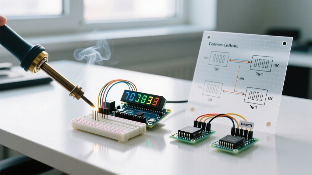

Introduction to 7-Segment Displays in Modern Prototyping
Despite the proliferation of high-resolution TFT and OLED screens, the classic 7-segment display remains a staple in industrial DIY, retro-computing, and high-visibility instrument panels in 2026. Their high luminous intensity, wide viewing angles, and robustness in high-EMI environments make them irreplaceable for specific applications. However, successfully integrating an Arduino and 7 segment display requires navigating specific electrical engineering constraints—namely forward voltage drops, current limiting, and multiplexing refresh rates.
This comprehensive wiring and code guide explores three distinct methodologies for driving these displays using the Arduino Uno R4 Minima (the current 2026 standard): direct GPIO wiring, MAX7219 SPI multiplexing, and TM1637 I2C interfacing. We will cover exact electrical calculations, pinouts, and production-ready C++ code.
Hardware Selection: Bare LEDs vs. Driver Modules
Before writing code, you must select the right hardware for your pinout budget and power requirements. Below is a comparison of the most common modules used by electrical engineers and hobbyists today.
| Display Type | Model / Chipset | Interface | Pins Required | Avg. Cost (2026) | Best Use Case |
|---|---|---|---|---|---|
| Bare Common Cathode | Kingbright SC56-11GWA | Direct GPIO | 8 (per digit) | $1.85 | Custom PCBs, single-digit indicators |
| SPI Multiplexed | MAX7219 8-Digit Module | SPI | 3 (DIN, CS, CLK) | $4.50 | Multi-digit counters, daisy-chaining |
| I2C-like Serial | TM1637 4-Digit Module | Custom 2-Wire | 2 (CLK, DIO) | $2.10 | Clocks, timers, quick prototyping |
Method 1: Direct Wiring (The Educational Approach)
Wiring a bare common cathode display directly to an Arduino's digital pins is the most fundamental method. While it consumes a massive amount of I/O pins (8 pins for a single digit, excluding the common ground), it is essential for understanding the underlying electrical behavior of the segments.
Electrical Calculations & Resistor Selection
Never connect a 7-segment display directly to a 5V logic pin without current-limiting resistors. According to SparkFun's LED engineering guide, exceeding the forward current ($I_f$) rating will cause rapid thermal degradation of the GaAsP/GaP junctions.
For a standard red Kingbright display, the forward voltage ($V_f$) is typically 2.0V, and the recommended continuous forward current is 15mA. Using a 5V Arduino Uno R4:
Ohm's Law Calculation:
$R = (V_{source} - V_f) / I_f$
$R = (5.0V - 2.0V) / 0.015A = 200\Omega$
The nearest standard E12 resistor value is 220Ω. If you are using blue or white 7-segment displays, $V_f$ jumps to ~3.2V, requiring a 120Ω resistor. Always place the resistor on the anode side of each segment (pins a through g) to prevent uneven brightness caused by varying internal trace resistances.
Direct Wiring Pinout & C++ Code
Connect the common cathode (pins 3 and 8 on a standard 10-pin DIP package) to the Arduino GND. Connect segments A through G to digital pins 2 through 8 via 220Ω resistors.
// Byte array mapping hex digits to segment pins (DP, G, F, E, D, C, B, A)
const byte seg_map[10] = {
  B00111111, // 0
  B00000110, // 1
  B01011011, // 2
  B01001111, // 3
  B01100110, // 4
  B01101101, // 5
  B01111101, // 6
  B00000111, // 7
  B01111111, // 8
  B01101111  // 9
};

const int segPins[8] = {2, 3, 4, 5, 6, 7, 8, 9};

void setup() {
  for (int i = 0; i < 8; i++) {
    pinMode(segPins[i], OUTPUT);
  }
}

void displayDigit(int digit) {
  byte mask = seg_map[digit];
  for (int i = 0; i < 8; i++) {
    digitalWrite(segPins[i], bitRead(mask, i));
  }
}

void loop() {
  for (int i = 0; i < 10; i++) {
    displayDigit(i);
    delay(1000);
  }
}
Method 2: MAX7219 SPI Multiplexing for Multi-Digit Arrays
When scaling beyond two digits, direct wiring becomes impossible due to pin exhaustion and the inability of the Arduino's ATmega32U4/Renesas RA4M1 microcontroller to source enough current without ghosting. The MAX7219 LED driver solves this by handling high-frequency multiplexing in hardware.
The Analog Devices MAX7219 datasheet specifies that the chip can drive up to 8 digits (or 64 individual LEDs) while requiring only three microcontroller pins via the SPI bus. It also features an internal 10MHz oscillator and hardware multiplexing, completely eliminating the flickering associated with software-based timer interrupts.
SPI Wiring & LedControl Implementation
- VCC: 5V (Ensure your power supply can deliver at least 500mA for an 8-digit module).
- GND: Common ground with Arduino.
- DIN: Arduino Pin 11 (MOSI).
- CS (LOAD): Arduino Pin 10 (SS).
- CLK: Arduino Pin 13 (SCK).
Using the widely adopted LedControl library, the code abstracts the SPI bit-shifting. Note that the MAX7219 requires an external current-setting resistor ($R_{set}$) on pin 18. Most commercial modules include a 10kΩ surface-mount resistor pre-soldered, which sets the segment current to ~20mA.
#include 'LedControl.h'

// Pins: DIN=11, CLK=13, CS=10, 1 device
LedControl lc = LedControl(11, 13, 10, 1);

void setup() {
  // Wake up the MAX7219 from power-saving mode
  lc.shutdown(0, false);
  // Set brightness to a medium level (0-15)
  lc.setIntensity(0, 8);
  lc.clearDisplay(0);
}

void loop() {
  for (int i = 0; i < 100; i++) {
    int tens = i / 10;
    int ones = i % 10;
    lc.setDigit(0, 1, tens, false);
    lc.setDigit(0, 0, ones, false);
    delay(250);
  }
}
Method 3: TM1637 I2C (The 2026 Prototyping Standard)
For rapid prototyping where 4 digits are sufficient (e.g., digital clocks, temperature readouts), the TM1637 module is the undisputed king. It uses a custom 2-wire serial protocol that mimics I2C but operates on any two digital pins. At roughly $2.10 per unit, it includes the display, driver IC, and current-limiting circuitry on a single PCB.
Wiring is trivial: connect CLK to Pin 2 and DIO to Pin 3. Utilizing the TM1637Display library by Avishay Orpaz, rendering numbers requires only a single function call.
#include

#define CLK 2
#define DIO 3

TM1637Display display(CLK, DIO);

void setup() {
  display.setBrightness(0x0a); // Set brightness (0x00 to 0x0f)
}

void loop() {
  display.showNumberDec(1024, false); // Display 1024
  delay(1000);
  display.showNumberDecEx(25, 0b11100000, true); // Display 2.5 (with decimal point)
  delay(1000);
}
Troubleshooting Edge Cases & Failure Modes
Even with correct wiring, engineers frequently encounter specific failure modes when integrating an Arduino and 7 segment display. Use this diagnostic matrix to resolve them:
1. Ghosting and Bleeding (Software Multiplexing)
If you are multiplexing bare displays using NPN transistors (like the 2N2222) and software delays, you may see faint illumination on adjacent digits. This 'ghosting' occurs because the Arduino's GPIO pins cannot discharge the parasitic capacitance of the LED segments fast enough during the dead-time between digit switching.
Fix: Implement a 1ms 'blanking' delay in your code where all segment pins are pulled LOW before switching the common cathode transistor to the next digit. Alternatively, add a 10kΩ pull-down resistor from the transistor base to GND to ensure rapid cutoff.
2. Flickering on Long SPI Runs (MAX7219)
The MAX7219 relies on high-speed SPI. If your wiring exceeds 30cm, the capacitance of the jumper wires will degrade the square-wave clock signal, leading to corrupted shift registers and random flickering segments.
As noted in the official Arduino SPI reference, signal integrity degrades at higher clock speeds. If using long wires, you must lower the SPI clock divider in your initialization code, or buffer the SPI lines using a 74HC125 logic buffer.
3. Dim or Uneven Brightness (Direct Wiring)
If segment 'A' appears noticeably dimmer than segment 'B' on a bare display, you are likely victim to voltage sag on the Arduino's internal microcontroller traces. Sourcing 15mA through 8 pins simultaneously pulls over 120mA through the MCU's internal VCC ground plane.
Fix: Never source multi-digit bare displays directly from the MCU. Always use a ULN2803 Darlington transistor array for the cathodes and PNP transistors (like BC327) for the anodes, or migrate to a dedicated driver IC like the MAX7219.