
The Challenge of Multi-Peripheral Stepper Control
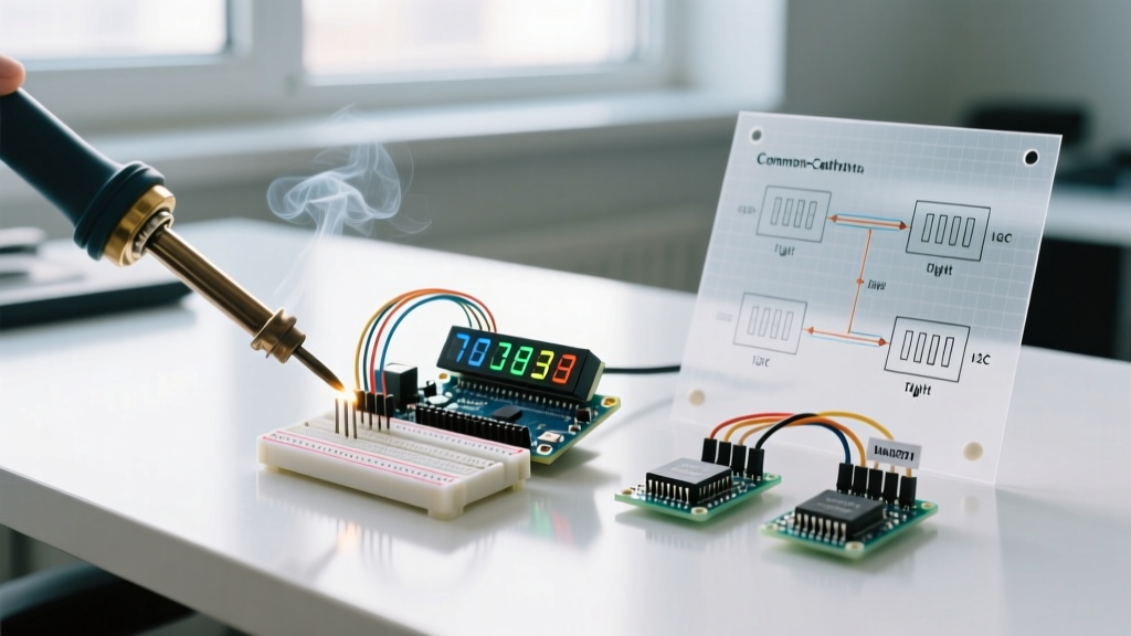
Integrating a stepper motor and driver Arduino setup into a larger multi-peripheral ecosystem is one of the most common stumbling blocks in advanced DIY electronics. When you are building automated camera sliders, CNC plotters, or precision lab equipment, the stepper motor cannot exist in a vacuum. It must operate concurrently with I2C OLED displays, optical limit switches, and environmental sensors.
The primary challenge is twofold: electrical noise and software blocking. Stepper motors generate massive back-EMF and draw high transient currents, which can easily corrupt sensitive I2C data buses or cause microcontroller brownouts. Simultaneously, generating the precise pulse trains required for smooth microstepping often leads beginners to use blocking delay() functions, freezing the entire system and preventing sensor polling. In this 2026 guide, we will architect a robust, non-blocking multi-peripheral system using modern hardware and advanced wiring techniques.
Hardware Selection: Moving Beyond the A4988
While the classic A4988 and DRV8825 drivers are still available, modern multi-peripheral setups demand silence, UART configurability, and advanced stall detection. As of 2026, the Trinamic TMC2209 is the undisputed gold standard for precision Arduino projects.
| Component | Model / Specification | Estimated Cost (2026) | Role in Multi-Peripheral Setup |
|---|---|---|---|
| Stepper Motor | NEMA 17 (StepperOnline 17HS19-2004S1) | $14.00 - $18.00 | Provides 59 N·cm holding torque; bipolar 4-wire configuration. |
| Motor Driver | BigTreeTech TMC2209 V1.2 | $6.50 - $9.00 | UART configuration, StealthChop2 for silent operation, hardware stallGuard. |
| Microcontroller | Arduino Nano Every (ATmega4809) | $12.00 - $15.00 | Features superior hardware timers and true 5V logic compared to standard Nano clones. |
| Display | 1.3" SH1106 I2C OLED (128x64) | $4.50 - $6.00 | Real-time telemetry display for position, speed, and sensor data. |
| Limit Switches | Omron D2F-L (Optical/Micro) | $2.00 - $3.50 | Homing and boundary protection with bounce-free signal transmission. |
Power Architecture: Isolating the Noise
The most critical failure mode in a multi-peripheral stepper motor and driver Arduino build is sharing power rails. When the stepper motor coils are energized, voltage dips on the main supply can reset the Arduino or corrupt the I2C bus, causing the OLED display to fill with static or freeze entirely.
The Dual-Rail Power Strategy
Never power the motor VMOT pin from the same 5V regulator that powers your Arduino and sensors. Instead, use a dedicated 24V DC power supply for the TMC2209 VMOT pin. The TMC2209 features an internal 5V logic regulator, but for multi-peripheral setups, you should power the driver's logic VIO pin directly from the Arduino's clean 5V rail to ensure perfect logic level matching.
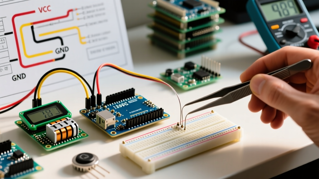
Expert Decoupling Rule: You must solder a 100µF electrolytic capacitor and a 0.1µF ceramic capacitor directly across the VMOT and GND pins of the TMC2209, as physically close to the IC as possible. This absorbs high-frequency switching noise before it propagates back to your power supply.
Fixing I2C Bus Capacitance and Pull-Up Issues
When you add an OLED display, a BME280 sensor, and the TMC2209 UART/I2C lines to the same bus, the parasitic capacitance increases. The standard 4.7kΩ I2C pull-up resistors found on most Arduino sensor breakouts become too weak, resulting in rounded signal edges and communication timeouts.
- Calculate the Pull-Up: For a 400kHz I2C bus with high capacitance, target a 3mA pull-up current. Using Ohm's law: (5V - 0.4V) / 0.003A = 1533Ω.
- The Fix: Desolder the 4.7kΩ surface-mount resistors on your OLED and add external 1.5kΩ or 2.2kΩ pull-up resistors directly to the SDA and SCL lines near the microcontroller.
Step-by-Step Wiring Matrix
Proper pin assignment prevents interrupt conflicts. The Arduino Nano Every has specific pins optimized for hardware timers and external interrupts, which we leverage for the limit switches and step pulses.
| Arduino Nano Every Pin | Destination | Function / Notes |
|---|---|---|
| D2 (INT0) | Omron Limit Switch (Left) | Hardware interrupt for immediate homing stop. |
| D3 (INT1) | Omron Limit Switch (Right) | Hardware interrupt for boundary protection. |
| D6 | TMC2209 STEP | Pulse generation (use Timer1 for hardware stepping). |
| D7 | TMC2209 DIR | Direction control logic. |
| D8 | TMC2209 UART TX/RX | Use a 1kΩ resistor between TX and RX for single-wire UART. |
| A4 (SDA) | SH1106 OLED & Sensors | I2C Data (with external 2.2kΩ pull-up). |
| A5 (SCL) | SH1106 OLED & Sensors | I2C Clock (with external 2.2kΩ pull-up). |
Non-Blocking Software Architecture
To read sensors, update an OLED, and move a stepper motor simultaneously, you must abandon delay(). The AccelStepper library by Mike McCauley remains the most reliable way to handle non-blocking motion profiles, provided you call stepper.run() on every iteration of the main loop.
Managing I2C Blocking Times
Updating a 128x64 OLED display via I2C takes approximately 4 to 8 milliseconds. If you call the display update function inside the main loop without a timer, the display refresh will bottleneck your step pulse generation, causing the motor to stutter or miss steps at high RPMs.
The Solution: Implement a millis()-based state machine to throttle display updates to 10Hz (every 100ms), while allowing the stepper loop and sensor polling to run at full speed.
unsigned long lastDisplayUpdate = 0;

void loop() {
  // 1. Non-blocking stepper execution (runs every loop iteration)
  stepper.run();

  // 2. High-speed sensor polling
  readEnvironmentalSensors();

  // 3. Throttled I2C Display Update (10Hz)
  if (millis() - lastDisplayUpdate >= 100) {
    lastDisplayUpdate = millis();
    updateOLEDDisplay(stepper.currentPosition(), stepper.speed());
  }
}
Troubleshooting Common Failure Modes
Even with perfect wiring, multi-peripheral setups present unique edge cases. Here is how to diagnose the most common issues encountered in 2026 builds.
1. Motor Stalls When OLED Updates
Cause: The I2C bus is monopolizing the microcontroller's processing time, causing the STEP pin to miss its timing window.
Fix: If using an AVR-based Arduino, switch to a library like U8g2 and utilize its asynchronous page-buffer drawing mode. Alternatively, upgrade to an ESP32 or Arduino Nano RP2040 Connect, which feature dual cores—dedicating one core exclusively to stepper pulse generation via hardware timers.
2. TMC2209 Overheating and Thermal Shutdown
Cause: Relying solely on the Vref potentiometer without configuring the UART current limits.
Fix: According to the official Trinamic TMC2209 datasheet, the driver uses an internal sense resistor network. Set the physical Vref potentiometer to a safe baseline (approx 1.2V), but use the TMC2209 UART library to set the IRUN current dynamically in software. This allows you to lower the holding current (IHOLD) to 30% when the motor is stationary, drastically reducing heat generation.
3. Erratic Limit Switch Triggering
Cause: Electromagnetic interference (EMI) from the stepper motor cables inducing phantom voltages in the limit switch signal wires.
Fix: Never run limit switch signal wires parallel to stepper motor coil wires. If they must cross, cross them at a strict 90-degree angle. Additionally, enable the internal Arduino pull-up resistors (INPUT_PULLUP) and place a 0.1µF ceramic capacitor between the switch signal pin and GND to filter out high-frequency EMI spikes.
References and Further Reading
- Texas Instruments Application Report: Understanding Stepper Motor Drivers (SLVA714) - Excellent deep dive into current regulation decay modes.
- Analog Devices: TMC2209 Datasheet - Essential for calculating UART current scaling and StealthChop thresholds.
- Mike McCauley: AccelStepper Library Documentation - The definitive guide to non-blocking motion profiles on 8-bit and 32-bit MCUs.