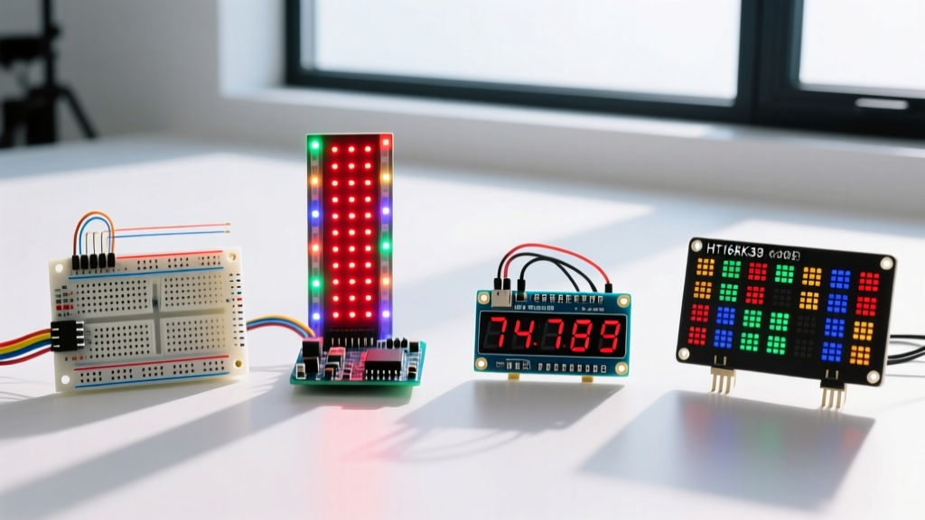

The LED Display Arduino Dilemma in 2026
When architects and hobbyists search for the ideal led display arduino solution, they are immediately confronted with a fragmented market of legacy drivers and modern addressable arrays. In 2026, component availability has stabilized, but the engineering constraints of power injection, bus capacitance, and library overhead remain the primary failure points in display integration. Selecting the wrong module doesn't just result in poor visuals; it can brownout your microcontroller or cause cascading data corruption.
This guide compares the four dominant LED architectures used with Arduino ecosystems today: the MAX7219 Dot Matrix, WS2812B RGB Matrices, TM1637 7-Segment displays, and the HT16K33 I2C Backpack. We will dissect exact power requirements, wiring edge cases, and the specific libraries required to drive them reliably.
Quick Comparison Matrix: 2026 Specifications
| Module Architecture | Protocol | Typical Resolution | Peak Current Draw | Avg. Price (2026) | Best Use Case |
|---|---|---|---|---|---|
| MAX7219 (4-in-1) | SPI | 32x8 (256 LEDs) | ~350mA | $4.50 | Scrolling text, retro gaming |
| WS2812B Matrix | 1-Wire PWM | 16x16 (256 RGB) | 15.3A (Full White) | $14.00 | Full-color animations, IoT dashboards |
| TM1637 | Custom 2-Wire | 4-Digit 7-Segment | ~20mA | $1.50 | Telemetry, timers, sensor readouts |
| HT16K33 Backpack | I2C | 16x8 (128 LEDs) | ~150mA | $9.99 | Complex UI, multi-display I2C buses |
MAX7219 Dot Matrix: The Scrolling Text Workhorse
The MAX7219 is a serially connected, common-cathode LED driver. Usually sold as a '4-in-1' 32x8 module, it communicates via SPI. While it is incredibly cheap and relies on the robust Arduino SPI hardware library, it is notorious for two specific failure modes in DIY deployments.
Failure Mode 1: Ghosting and Flicker
Most bare-bones MAX7219 PCBs omit adequate decoupling capacitors. When multiplexing 64 LEDs simultaneously, the instantaneous current draw causes micro-voltage drops on the VCC rail, resulting in 'ghosting' (faint illumination of adjacent LEDs) or severe flickering.
- The Fix: Solder a 100nF (0.1µF) ceramic capacitor directly across the VCC and GND pins of the MAX7219 IC on the PCB, and add a 10µF electrolytic capacitor at the power input header of the module chain.
Failure Mode 2: Cascading Limits and Signal Degradation
The SPI data line (DIN) passes through each module sequentially. Beyond four cascaded modules, the parasitic capacitance of the long copper traces degrades the square wave, causing the 5th or 6th module to display garbage data.
- The Fix: If your project requires more than 4 modules, inject a 74HC14 hex inverter as a logic buffer halfway through the chain to clean the signal edges, or run parallel SPI buses from the Arduino using software SPI on secondary pins.
WS2812B RGB Matrices: The High-Current Visual Powerhouse
Addressable RGB matrices (often branded as NeoPixel) have become the standard for high-fidelity visual output. However, treating a 16x16 WS2812B matrix like a standard sensor module is a catastrophic mistake. According to the Adafruit NeoPixel Uberguide, a single WS2812B pixel draws up to 60mA at full white brightness.
Power Injection Math & Hardware
A 16x16 matrix contains 256 pixels. 256 pixels x 60mA = 15,360mA (15.36 Amps). You absolutely cannot power this from the Arduino's 5V pin, which is typically limited to 500mA via USB or 1A via the onboard linear regulator.
- Required PSU: A dedicated 5V 20A (100W) switching power supply.
- Wiring Topology: Power must be injected at both the top and bottom copper pads of the flexible matrix PCB to prevent voltage drop across the thin internal traces, which can cause the bottom rows to shift from white to yellow/red.
- Protection: A 1000µF bulk capacitor across the main power rails and a 470Ω resistor on the data line before the first pixel are mandatory to prevent inductive spikes from frying the first IC.
Library Selection: FastLED vs. Adafruit_NeoPixel
For complex matrix mapping in 2026, the FastLED library is vastly superior to the legacy Adafruit library. FastLED supports hardware-accelerated SPI output on modern microcontrollers and includes built-in color correction profiles and dithering algorithms that eliminate the low-end color banding inherent to 8-bit PWM LEDs.
TM1637 7-Segment: The Minimalist Telemetry Display
The TM1637 4-digit 7-segment display is the undisputed king of simple numeric readouts. It requires only two data pins (CLK and DIO) and costs roughly $1.50. However, developers frequently mistake its protocol for standard I2C.
The 'Fake I2C' Trap
The TM1637 uses a proprietary synchronous serial protocol that mimics I2C but lacks hardware addressing and ACK/NACK handshaking. Because it is not true I2C, you should never place standard 4.7kΩ I2C pull-up resistors on the CLK and DIO lines. Doing so will alter the rise times and cause the display to lock up or flicker randomly.
Capacitance and Wire Length
The TM1637 operates with very weak internal pull-ups. If you route the CLK and DIO wires longer than 25cm, the cable capacitance will round off the signal edges, leading to missed digits.
- Actionable Advice: Keep jumper wires under 15cm. If long runs are unavoidable, use a dedicated I2C bus extender like the P82B715, or switch to a true I2C display like the HT16K33.
HT16K33 I2C Backpack: The Premium Prototyper's Choice
Holtek's HT16K33 driver, usually sold mounted on an Adafruit or generic 'LED Backpack' PCB, is a true I2C device featuring an internal RAM buffer and hardware dimming. While a 16x8 matrix version costs around $9.99—twice the price of a MAX7219 equivalent—it solves almost all bus-timing issues.
Multi-Display Addressing
Unlike the SPI-based MAX7219 which requires daisy-chaining, the HT16K33 features three address jumpers on the PCB. This allows you to wire up to eight separate 16x8 matrices on the exact same SDA and SCL lines, each drawing only ~20mA of logic current (LED power is drawn directly from VCC). This makes it the ultimate choice for modular dashboards where multiple distinct readouts are required without the signal degradation of long SPI chains.
Decision Framework: Which LED Display Arduino Setup Wins?
Use this framework to finalize your component selection based on your project constraints:
- Choose MAX7219 if: You need monochromatic scrolling text, are on a strict sub-$5 budget, and your physical layout allows for a straight, short SPI daisy-chain.
- Choose WS2812B if: Your project demands full RGB color mapping, high frame-rate animations, and you have the physical space and budget for a heavy-duty 5V external power supply.
- Choose TM1637 if: You only need to display simple integers (like a temperature readout or countdown timer), have limited GPIO pins, and can mount the display directly adjacent to the microcontroller.
- Choose HT16K33 if: You are building a complex I2C sensor dashboard requiring multiple independent matrix displays and demand rock-solid bus stability without software-level bit-banging.
Frequently Asked Questions
Can I power a small 8x8 WS2812B matrix directly from the Arduino 5V pin?
An 8x8 WS2812B matrix contains 64 pixels. At maximum white brightness, it will attempt to draw 3.8 Amps. This will instantly trip the polyfuse on an Arduino Uno's USB line or destroy the onboard 5V linear regulator if using the barrel jack. You must limit the global brightness to roughly 5% in software (using FastLED's setBrightness(12) function) to keep the draw under 300mA, or use an external 5V PSU.
Why does my MAX7219 display random characters when a relay switches on?
The MAX7219 SPI bus is highly susceptible to Electromagnetic Interference (EMI) generated by inductive loads like relays and solenoids. The voltage spike couples into the high-impedance SPI clock line, shifting the data bits. Route SPI cables away from relay coils, use twisted-pair wiring for the SPI bus, and ensure your relay module has opto-isolators and flyback diodes installed.