
The Ultimate Troubleshooting Guide for I2C LCD Modules
Integrating a 16x2 or 20x4 character LCD into your microcontroller project is a rite of passage for electronics hobbyists and engineers alike. However, when your arduino code lcd display setup results in a blank screen, garbage characters, or compilation errors, the root cause is rarely the LCD glass itself. In 2026, the vast majority of these displays utilize an I2C backpack based on the PCF8574 or PCF8574A I/O expander chips, bridging the parallel HD44780 controller to a two-wire serial bus.
This guide bypasses generic advice and dives deep into the specific hardware failure modes, logic-level mismatches, and library conflicts that plague I2C LCD integrations. Whether you are using a standard 5V Arduino Uno R3 or a 3.3V ESP32, these diagnostic steps will isolate and resolve your display issues.
Phase 1: Hardware Wiring and Power Diagnostics
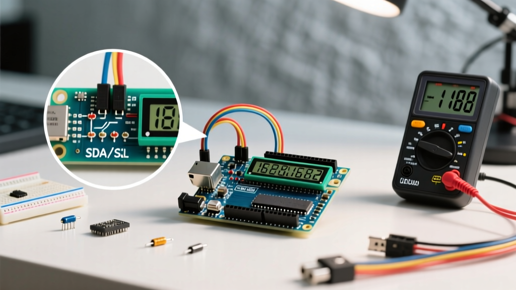
Before modifying your arduino code lcd display scripts, you must verify the physical layer. I2C is highly sensitive to missing pull-up resistors and incorrect voltage rails. Standard I2C backpacks require a strict 5V supply to operate the LCD logic and backlight LEDs properly.
Standard I2C Backpack Pinout Matrix
| Backpack Pin | Arduino Uno/Nano | Arduino Mega 2560 | Function & Notes |
|---|---|---|---|
| GND | GND | GND | Common ground reference. Must be shared with MCU. |
| VCC | 5V | 5V | Do NOT use 3.3V. The backlight requires ~4.2V minimum. |
| SDA | A4 | Pin 20 | Serial Data. Requires 4.7kΩ pull-up to VCC. |
| SCL | A5 | Pin 21 | Serial Clock. Requires 4.7kΩ pull-up to VCC. |
Expert Insight: Many cheap clone I2C backpacks omit the 4.7kΩ pull-up resistors on the SDA and SCL lines. While the Arduino's internal weak pull-ups (approx. 20kΩ-50kΩ) might barely work on short jumper wires, any wire longer than 15cm will introduce capacitance that corrupts the I2C signal. Always solder external 4.7kΩ resistors between VCC and the SDA/SCL pins for reliable operation.
Phase 2: The Contrast Potentiometer Trap
If your LCD backlight is illuminated (usually blue with white text, or green with black text) but the screen is completely blank, the issue is almost always the contrast voltage (V0). On the back of the I2C backpack, you will find a small blue trimpot (a 10K ohm variable resistor).
- The Physics of V0: The HD44780 controller requires the V0 pin to sit at a specific negative voltage relative to VDD (typically around 0.5V to 1.0V above ground) to activate the liquid crystals.
- The Fix: Use a small Phillips or flathead screwdriver to turn the trimpot. Rotate it slowly clockwise and counter-clockwise. You will suddenly see a row of dark blocks appear. Stop adjusting once the blocks are just barely visible; this provides the highest contrast ratio for standard viewing angles.
Phase 3: Hunting the Correct I2C Address
The most common reason for arduino code lcd display failure is initializing the software with the wrong I2C address. Manufacturers use two primary I/O expander chips on these backpacks, and they have different factory-default addresses.
- PCF8574T (Texas Instruments/NXP): Default address is
0x27. - PCF8574AT (NXP): Default address is
0x3F.
According to the official NXP PCF8574 datasheet, the address is determined by the state of the A0, A1, and A2 pins on the chip. Most backpacks leave these pulled high, but you can verify your exact address using the standard Wire scanner script.
I2C Address Scanner Code
#include <Wire.h>

void setup() {
  Wire.begin();
  Serial.begin(115200);
  while (!Serial); // Wait for serial monitor
  Serial.println("\nI2C Scanner");
}

void loop() {
  byte error, address;
  int nDevices = 0;
  for(address = 1; address < 127; address++ ) {
    Wire.beginTransmission(address);
    error = Wire.endTransmission();
    if (error == 0) {
      Serial.print("I2C device found at address 0x");
      if (address < 16) Serial.print("0");
      Serial.println(address, HEX);
      nDevices++;
    }
  }
  if (nDevices == 0) Serial.println("No I2C devices found\n");
  delay(5000); // Scan every 5 seconds
}
Upload this to your board and open the Serial Monitor at 115200 baud. If it returns 0x27 or 0x3F, note it down for your main sketch. If it returns nothing, you have a wiring or power fault.
Phase 4: Resolving Library Conflicts in 2026
A massive source of frustration in the Arduino ecosystem is the fragmentation of LCD libraries. Historically, users relied on the LiquidCrystal_I2C library by Frank de Brabander. However, this library is largely abandoned, frequently conflicts with the built-in LiquidCrystal library, and hardcodes pin mappings that fail on newer PCF8574 backpack variants.
The Modern Standard: hd44780 Library
For any new project, you should exclusively use the hd44780 library developed by Bill Perry. It auto-detects the I2C address and the specific pin mapping of the backpack, eliminating the need to manually configure constructor arguments. You can install it directly via the Arduino Library Manager by searching for 'hd44780'.
Here is the bulletproof initialization code using the modern library:
#include <Wire.h>
#include <hd44780.h>
#include <hd44780ioClass/hd44780_I2Cexp.h>

// Auto-detects I2C address and pin mappings
hd44780_I2Cexp lcd;

void setup() {
  // Initialize LCD with 16 columns and 2 rows
  int status = lcd.begin(16, 2);

  // Check if initialization failed
  if (status != 0) {
    // Use fatal error blink codes if I2C fails
    hd44780::fatalError(status);
  }

  lcd.print("System Online");
  lcd.setCursor(0, 1);
  lcd.print("Flux Diagnostics");
}

void loop() {
  // Main loop logic
}
Phase 5: Logic Level Mismatches (3.3V vs 5V)
As the industry shifts toward 3.3V microcontrollers like the ESP32, Raspberry Pi Pico (RP2040), and Arduino Due, a critical hardware danger emerges. Standard I2C LCD backpacks operate at 5V. If you connect a 3.3V MCU directly to a 5V I2C bus, two things happen:
- Garbage Characters: The 3.3V HIGH signal from the MCU may not cross the 5V logic threshold (V_IH) of the PCF8574 chip, resulting in corrupted data packets and random Japanese characters on the screen.
- Silicon Damage: The 5V pull-ups on the LCD backpack will feed 5V back into the 3.3V SDA/SCL pins of your ESP32, potentially degrading or destroying the GPIO pads over time.
The Solution: You must use a bidirectional logic level converter (LLC). A BSS138 MOSFET-based LLC module (typically costing around $1.20 to $1.80 in 2026) safely translates the 3.3V I2C signals to 5V. Connect the LV side to your MCU's 3.3V and the HV side to the LCD's 5V rail. For comprehensive bus architecture guidelines, refer to the official Arduino I2C communication documentation.
Expert Troubleshooting Matrix
Use this rapid-diagnosis matrix to identify your specific failure mode based on visual symptoms.
| Visual Symptom | Probable Root Cause | Targeted Fix |
|---|---|---|
| Backlight ON, completely blank screen | V0 contrast voltage out of spec | Adjust blue trimpot on backpack until blocks appear. |
| Top row of solid black blocks | HD44780 controller failed to initialize | Check 5V power rail; add 100uF decoupling capacitor across VCC/GND. |
| Garbage / Random Kanji characters | I2C noise or logic level mismatch | Add 4.7k pull-ups; use BSS138 logic level shifter for 3.3V MCUs. |
| Display works, but backlight is OFF | Backlight jumper missing or code toggle | Short the 'LED' jumper pins on the backpack; ensure code doesn't call lcd.noBacklight(). |
| Compilation Error: 'LiquidCrystal_I2C' not found | Library path conflict or deprecation | Uninstall old libraries; switch to hd44780 via Library Manager. |
Final Diagnostics
By methodically verifying the 5V power delivery, tuning the V0 contrast threshold, scanning for the precise PCF8574 I2C address, and migrating to the auto-detecting hd44780 library, you will eliminate 99% of all arduino code lcd display integration failures. Always remember that I2C is an open-drain bus; it relies entirely on proper pull-up resistors and clean voltage thresholds to maintain data integrity across your peripheral network.