
Beyond the Basic Tutorial: Why the L298N Datasheet Matters
The L298N dual full-bridge driver is arguably the most ubiquitous motor controller in the DIY electronics and Arduino ecosystem. Priced between $3.00 and $5.00 on most hobbyist marketplaces in 2026, it is the default choice for educational robotics and basic automation. However, most online tutorials treat the module as a magical black box, ignoring the underlying silicon realities. To build reliable, non-overheating projects, you must understand the STMicroelectronics L298 official product specifications. This guide decodes the datasheet, translating abstract bipolar junction transistor (BJT) parameters into actionable wiring rules, thermal limits, and voltage expectations for Arduino UNO and Mega integrations.
The Bipolar Penalty: Decoding the Voltage Drop
Unlike modern MOSFET-based drivers that boast milliohm-level on-resistance, the L298N utilizes an older bipolar transistor architecture. The datasheet specifies a saturation voltage ($V_{CE(sat)}$) for the internal transistors. Because an H-bridge routes current through two transistors in series (one high-side, one low-side), you must double this value to find the total voltage drop across the driver.
Datasheet Reality Check: At a continuous current of 1A, the typical $V_{CE(sat)}$ per transistor is 1.0V. This means the module drops roughly 2.0V before the electricity ever reaches your motor. At the maximum rated 2A, this drop spikes to nearly 3.2V.
This voltage drop has massive implications for your power supply planning. If you feed the module 12V, your 12V DC motor will only see about 9.5V to 10V under load, resulting in reduced torque and RPM. The table below illustrates real-world motor voltage expectations based on your input supply.
| Power Supply ($V_S$) | Expected Motor Voltage (at 1A Load) | Expected Motor Voltage (at 2A Load) | Power Dissipated as Heat |
|---|---|---|---|
| 12.0V | ~10.0V | ~8.8V | 2.0W to 3.2W |
| 9.0V | ~7.0V | ~5.8V | 2.0W to 3.2W |
| 7.4V (2S LiPo) | ~5.4V | ~4.2V | 2.0W to 3.2W |
| 5.0V (USB/Logic) | ~3.0V (Insufficient for most 6V+ motors) | ~1.8V | 2.0W to 3.2W |
Actionable Advice: Always over-specify your power supply voltage by at least 2.5V to 3V above your motor's nominal rating to compensate for the BJT saturation penalty. If you are driving a standard 12V gear motor, a 14V or 15V supply is ideal, provided it does not exceed the module's absolute maximum ratings.
The 2-Amp Myth: Thermal Resistance and Shutdown Limits
The L298N datasheet boldly advertises a "2A maximum current per channel." While technically true for brief peak bursts, attempting to pull a continuous 2A per channel (4A total) on a standard hobbyist module will trigger the chip's internal thermal shutdown almost immediately. To understand why, we must look at the thermal resistance parameter ($R_{th(j-amb)}$).
For the Multiwatt15 package used on these modules, the junction-to-ambient thermal resistance is approximately 35 °C/W. Let us run the thermal math for a single channel driving a 1.5A motor stall current:
- Voltage Drop: At 1.5A, the total $V_{CE(sat)}$ drop is roughly 2.5V.
- Power Dissipation ($P_d$):strong> $2.5V \times 1.5A = 3.75W$ of pure heat generated inside the silicon.
- Temperature Rise: $3.75W \times 35 °C/W = 131.25 °C$ rise above ambient.
- Final Junction Temp ($T_j$):strong> Assuming a 25 °C room, $25 + 131.25 = 156.25 °C$.
The L298N features built-in thermal shutdown that triggers at approximately 150 °C. Therefore, a continuous 1.5A load in a standard room-temperature environment will cause the chip to shut itself off to prevent destruction. The small aluminum heatsinks glued onto cheap modules offer negligible improvement to the junction-to-ambient thermal path because the bottleneck is the internal silicon-to-case resistance, not the case-to-air resistance.
Real-World Limit: Treat the L298N as a 0.8A to 1.0A continuous driver per channel. If your motors draw more than 1A continuously, you must either implement active forced-air cooling directly on the chip or upgrade to a MOSFET-based driver.
Powering the Logic: $V_S$, $V_{SS}$, and the Onboard 7805
A common point of failure for beginners is misunderstanding the dual power domains of the L298N. The chip requires two separate voltage inputs:
- $V_S$ (Power Supply): The high-voltage input for the motors (pins 4 and 8 on the bare IC, routed to the green screw terminal on the module).
- $V_{SS}$ (Logic Supply): The low-voltage input for the internal logic gates (pin 9 on the bare IC, routed to the 5V pin on the module header).
Most L298N modules include an onboard LM7805 linear voltage regulator. This regulator takes the $V_S$ motor supply and steps it down to 5V to power the logic side, conveniently allowing you to power the Arduino via the module's 5V output pin. However, linear regulators dissipate excess voltage as heat. If you supply 24V to the motor terminal, the 7805 must drop 19V. Even a modest 50mA logic draw will cause the 7805 to overheat and fail.
The Jumper Rule: If your motor supply ($V_S$) is 12V or less, leave the 5V enable jumper in place. If your motor supply is greater than 12V, you must remove the jumper and supply 5V directly to the logic pin from your Arduino or a separate buck converter.
Flyback Diodes and PWM Frequency Constraints
Inductive loads like DC motors generate massive reverse voltage spikes (back-EMF) when the current is suddenly interrupted. The Adafruit Motor Selection Guide emphasizes that without flyback diodes, these spikes will instantly punch through the driver transistors. The L298N datasheet mandates external fast-recovery diodes.
Hobbyist modules typically include an array of eight 1N4007 diodes. While the 1N4007 is rated for 1A and 1000V, it is a standard recovery rectifier with a reverse recovery time ($t_{rr}$) of roughly 30µs. If you are using basic on/off control or low-frequency PWM (under 1 kHz), the 1N4007 is adequate. However, if you attempt high-frequency PWM (e.g., 20 kHz to push motor whine out of human hearing range), the slow recovery time of the 1N4007 will cause massive switching losses, severe EMI, and eventual diode failure. For high-frequency PWM applications, physically desolder the 1N4007s and replace them with UF4007 (ultra-fast) or Schottky diodes like the 1N5819.
Arduino UNO to L298N Wiring Matrix
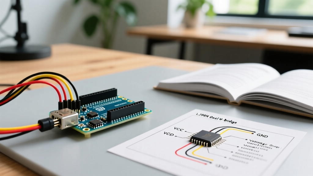
To implement bidirectional control and speed regulation via PWM, follow this exact pinout matrix for an Arduino UNO. This configuration isolates the PWM generation to hardware-timer pins to ensure clean signal output.
| L298N Module Pin | Arduino UNO Pin | Function & Configuration Notes |
|---|---|---|
| 12V / $V_S$ | N/A (External PSU) | Connect to positive terminal of battery pack (e.g., 9V-12V). |
| GND | GND | CRITICAL: Must share a common ground with the Arduino and PSU. |
| 5V / $V_{SS}$ | 5V (Optional) | Only connect if powering the Arduino from the module's 7805 regulator. |
| ENA (Enable A) | Pin 9 (PWM) | Controls speed of Motor A via analogWrite(). Remove physical jumper cap. |
| IN1 (Input 1) | Pin 8 (Digital) | Logic HIGH/LOW for Motor A direction. |
| IN2 (Input 2) | Pin 7 (Digital) | Logic HIGH/LOW for Motor A direction. |
| ENB (Enable B) | Pin 10 (PWM) | Controls speed of Motor B via analogWrite(). Remove physical jumper cap. |
| IN3 (Input 3) | Pin 6 (Digital) | Logic HIGH/LOW for Motor B direction. |
| IN4 (Input 4) | Pin 5 (Digital) | Logic HIGH/LOW for Motor B direction. |
Logic Control Truth Table
The internal logic gates of the L298N interpret the IN1/IN2 states as follows:
- Forward: IN1 = HIGH, IN2 = LOW
- Reverse: IN1 = LOW, IN2 = HIGH
- Coast (Free Spin): IN1 = LOW, IN2 = LOW (Motor disconnects from power, spins down naturally)
- Brake (Hard Stop): IN1 = HIGH, IN2 = HIGH (Motor terminals shorted together via low-side transistors, causing rapid deceleration)
2026 Perspective: When to Upgrade to MOSFET Drivers
While the L298N remains a staple for legacy curriculum and ultra-low-budget prototyping, modern robotics design has largely moved toward MOSFET-based H-bridges. If your project requires high efficiency, battery-powered operation, or high-frequency PWM, you should evaluate alternatives like the Pololu TB6612FNG Dual Motor Driver or the TI DRV8871.
The TB6612FNG utilizes MOSFETs with an on-resistance ($R_{DS(on)}$) of roughly 0.5Ω, compared to the L298N's effective 2.0Ω+ resistance. This means the TB6612FNG drops less than 0.5V at 1A, delivering nearly all your battery's voltage to the motor while running cool enough to require zero heatsinking. Furthermore, the TB6612FNG supports PWM frequencies up to 100 kHz, allowing for silent motor operation and highly responsive PID control loops. While a TB6612FNG module costs slightly more (typically $6.00 to $9.00), the gains in battery life, torque delivery, and thermal reliability make it the superior choice for any serious autonomous rover or robotic arm project in 2026.