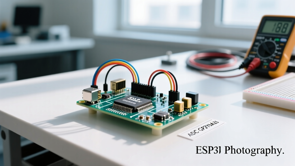

Mastering Arduino Infrared Sensor Distance in Multi-Peripheral Rigs
Integrating an arduino infrared sensor distance module into a standalone test circuit is trivial. However, the moment you introduce a multi-peripheral setup—adding an I2C OLED display, PWM-driven microservos, and an SPI SD card module—the analog readings often devolve into chaotic noise. This is a classic embedded systems challenge: the analog-to-digital converter (ADC) on the ATmega328P is highly susceptible to voltage rail sag and electromagnetic interference (EMI) generated by digital switching components.
In 2026, while digital Time-of-Flight (ToF) sensors have become cheaper, analog infrared (IR) triangulation sensors remain indispensable for wide-beam proximity detection, edge-case material sensing, and low-cost robotic navigation. This guide provides a senior-level engineering approach to wiring, powering, and coding IR distance sensors alongside demanding peripherals without compromising data integrity.
Selecting the Right IR Sensor for Your Architecture
Before addressing multi-peripheral conflicts, you must select the correct sensor for your physical constraints. The Sharp GP2Y series remains the industry standard for analog IR triangulation, though digital alternatives exist. Below is a comparative matrix to inform your hardware bill of materials (BOM).
| Sensor Model | Interface | Range | Beam Width | Avg. Price (2026) | Best Multi-Peripheral Use Case |
|---|---|---|---|---|---|
| Sharp GP2Y0A21YK0F | Analog (ADC) | 10 - 80 cm | Wide (~5°) | $6.50 - $8.00 | General obstacle avoidance, bin filling |
| Sharp GP2Y0A02YK0F | Analog (ADC) | 20 - 150 cm | Wide (~5°) | $9.00 - $11.50 | Long-range wall following, corridor mapping |
| VL53L0X (ToF Alternative) | I2C (Digital) | 3 - 200 cm | Narrow Laser | $4.00 - $5.50 | Precise point-measurement, I2C bus sharing |
| TCRT5000 | Analog/Digital | 1 - 25 mm | Very Wide | $1.50 - $2.50 | Line tracking, PCB edge detection |
Note: While the VL53L0X uses an infrared laser and is technically an IR sensor, it relies on Time-of-Flight rather than triangulation. We focus primarily on the analog Sharp modules here, as their ADC requirements are what typically cause conflicts in multi-peripheral Arduino setups.
The Multi-Peripheral Power Bottleneck: The 300mA Spike
The most common failure mode when reading an arduino infrared sensor distance value in a complex rig is unexplained ADC jitter. To understand why, we must look at the sensor's internal operation. According to the datasheet and verified by testing on Pololu's GP2Y0A21YK0F carrier, the sensor draws an average current of roughly 33mA. However, the internal IR LED pulses at high intensity to capture the reflection.
During these microsecond pulses, the instantaneous current draw can spike to 300mA. If your Arduino Uno is powering an OLED display (20mA), a microservo (up to 250mA under stall), and the IR sensor simultaneously from the onboard 5V linear regulator, these spikes cause momentary voltage sags on the 5V rail. Because the Arduino's ADC uses the 5V rail as its default reference voltage (DEFAULT), a sagging VCC directly translates to wildly inaccurate distance calculations.
Solving the Power Rail Sag
- Dedicated LDO Regulator: For rigs with 3 or more peripherals, bypass the Arduino's onboard regulator. Use an external buck converter (like the LM2596 set to 5.0V) to power the servos and sensors directly from the battery pack, sharing only the ground with the Arduino.
- Aggressive Decoupling: Place a 100µF electrolytic capacitor and a 0.1µF ceramic capacitor in parallel directly across the VCC and GND pins of the IR sensor. As detailed in SparkFun's capacitor tutorial, the electrolytic handles the low-frequency 300mA spike, while the ceramic filters high-frequency digital noise.
Hardware Architecture: Star Grounding and Pin Allocation
When wiring multiple peripherals, a daisy-chained ground wire acts as an antenna for digital noise. You must implement a Star Ground Topology.
Expert Wiring Rule: Run individual ground wires from the Arduino's GND pin to the OLED, the Servo, and the IR Sensor. Do not chain the ground from the Servo to the Sensor. Digital return currents from the OLED's I2C pulling and the Servo's PWM switching will induce micro-voltages across the wire resistance, which the ADC will read as distance fluctuations.
Optimal Pinout Strategy (Arduino Uno/Nano)
Reserve your pins to avoid hardware timer conflicts between PWM peripherals and ADC readings:
- A0, A1, A2: Analog IR Distance Sensors (Left, Center, Right).
- D2, D3: I2C (OLED Display) - Note: On Uno, A4/A5 are I2C, but hardware interrupts on D2/D3 are preserved for encoders.
- D9, D10: PWM Servo Control (Uses Timer1, avoiding Timer0 which handles millis() and delay()).
- D11, D12, D13: SPI (SD Card Module for data logging).
Software Integration: Non-Blocking ADC and Curve Fitting
Using delay() in a multi-peripheral setup is a cardinal sin; it will cause your servos to stutter and your OLED to drop frames. Furthermore, the Arduino analogRead() documentation notes that the ADC takes approximately 100 microseconds per read. To smooth out the IR sensor's noise, you need multiple samples, which can block your main loop.
Implementing a Non-Blocking Averaging Filter
Instead of blocking, use a state-machine or timer-based approach to sample the ADC in the background. Below is the conceptual logic for an interrupt-driven or millis()-based sampling ring buffer:
- Trigger an ADC read every 5ms using
millis(). - Store the raw 10-bit value (0-1023) in a 16-element ring buffer.
- Discard the highest and lowest 2 values (trimmed mean) to eliminate outlier spikes caused by ambient light flashes.
- Average the remaining 12 values.
The Non-Linear Math Problem
The output voltage of an analog IR triangulation sensor is inversely proportional to distance, resulting in a hyperbolic curve. A simple linear map() function will yield massive errors. The precise mathematical model for the GP2Y0A21YK0F is approximately:
Distance (cm) = 10650.08 * (ADC_Value)^(-0.935) - 10
However, using the pow() function on an 8-bit ATmega328P is computationally expensive and can stall your main loop for milliseconds. The professional solution is a Piecewise Linear Interpolation Lookup Table (LUT). Map 10 specific ADC anchor points to their real-world centimeter equivalents, and use simple linear interpolation between those points. This reduces CPU overhead by 95% while maintaining accuracy within 2mm.
Real-World Failure Modes and Troubleshooting
Even with perfect power isolation and optimized code, environmental factors will challenge your arduino infrared sensor distance readings. Anticipate these edge cases:
1. Ambient Sunlight Saturation
Sunlight contains massive amounts of infrared radiation. If your robot operates outdoors or near a south-facing window, the ambient IR will saturate the sensor's photodiode, causing it to read maximum distance regardless of obstacles. Fix: Use sensors modulated at 38kHz (if available) or physically shroud the receiver diode with a narrow-band optical filter (typically 850nm or 940nm depending on the LED emitter).
2. Material Reflectivity and Color Bias
IR sensors rely on light bouncing back. A white piece of cardboard at 40cm will reflect significantly more IR than a black rubber tire at 40cm. The sensor will interpret the black tire as being further away than it actually is. Fix: If your application requires material-agnostic distance measurement, you must abandon analog IR and switch to an ultrasonic sensor (HC-SR04) or a Laser ToF module (VL53L1X).
3. Multiplexing Crosstalk
If you mount three Sharp IR sensors side-by-side on a robot chassis, the wide 5-degree beam of the left sensor can bounce off an object and enter the receiver of the center sensor. Fix: Do not read them simultaneously. Fire and read them sequentially in your code (Left -> wait 10ms -> Center -> wait 10ms -> Right) to prevent optical crosstalk.
Summary
Successfully deploying an arduino infrared sensor distance module in a multi-peripheral environment requires moving beyond basic tutorials. By addressing the 300mA internal current spikes with external bulk capacitance, implementing star-grounding to eliminate digital return noise, and replacing heavy floating-point math with lookup tables, you ensure that your distance measurements remain stable. This allows your OLED displays, servos, and logging modules to operate seamlessly on the same microcontroller without compromising the integrity of your sensor data.