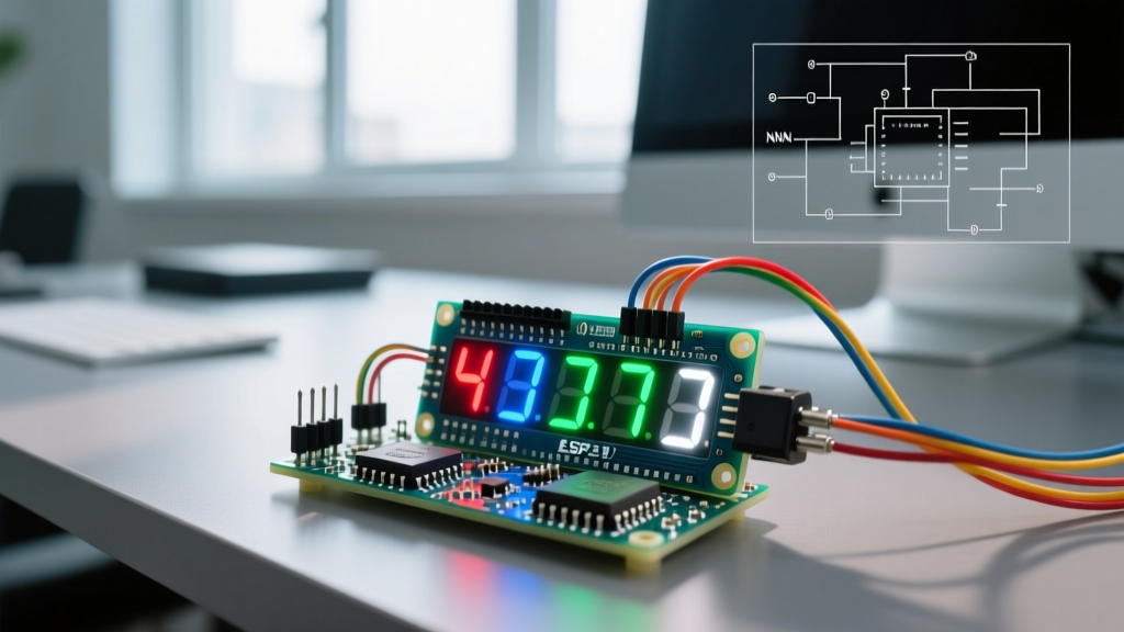

Introduction to 4 Digit 7 Segment Display Arduino Integration
Interfacing a 4 digit 7 segment display Arduino project is a foundational skill for embedded systems engineers and DIY electronics enthusiasts. While modern OLED and TFT screens offer pixel-level control, classic LED segment displays remain unmatched for high-visibility, low-latency numerical readouts in industrial dashboards, retro-fits, and high-temperature environments. As of 2026, the 0.56-inch 5641AS (Common Cathode) and 5161BS (Common Anode) models continue to dominate the market due to their exceptional nits-to-dollar ratio and robust operating temperature ranges (-40°C to 85°C).
However, driving a raw 12-pin multiplexed display is fundamentally different from using an I2C backpack. It requires a deep understanding of persistence of vision, current sinking, and timer-based multiplexing. This guide provides a comprehensive, expert-level wiring and code framework to ensure your display is bright, flicker-free, and safe for your microcontroller.
Component Selection: Raw 12-Pin vs. TM1637 Modules
Before soldering, you must decide between a raw 12-pin display and a pre-packaged module. The table below breaks down the engineering trade-offs for 2026 hardware revisions.
| Feature | Raw 12-Pin (5641AS / 5161BS) | TM1637 I2C-like Module |
|---|---|---|
| I/O Pin Requirement | 12 pins (without shift registers) | 2 pins (CLK, DIO) |
| Current Handling | Requires external transistors/drivers | Handled by onboard TM1637 IC |
| Custom PCB Integration | Excellent (low profile, flexible) | Poor (bulky module, fixed layout) |
| Avg. Unit Cost (2026) | $1.20 - $1.85 | $2.50 - $3.90 |
| CPU Overhead | High (requires timer interrupts) | Low (blocking I2C-like protocol) |
For custom PCB designs or learning core embedded concepts, the raw 12-pin display is the superior choice. For rapid prototyping on a breadboard, the TM1637 saves significant wiring time.
The Hidden Danger: Current Sinking and Digit Pins
CRITICAL HARDWARE WARNING: Never drive the common digit pins of a raw 4-digit display directly from an Arduino Uno/Nano ATmega328P I/O pin. If all 8 segments (including the decimal point) are illuminated simultaneously on a single digit, the current draw can exceed 160mA. The absolute maximum rating per I/O pin is 40mA, and the total port limit is 100mA. Direct connection will permanently degrade or destroy the microcontroller's silicon.
To safely drive a Common Cathode display like the 5641AS, you must use NPN transistors (e.g., 2N3904 or BC547) to sink the current from the digit pins to ground. For Common Anode displays (5161BS), you would use PNP transistors (e.g., 2N3906) to source current from VCC. Alternatively, you can use a dedicated driver IC like the ULN2003A (Darlington transistor array) or a Texas Instruments SN74HC595 shift register combined with transistors to save Arduino I/O pins.
Wiring the 5641AS (Common Cathode) with Transistors
Below is the professional wiring standard for a 5641AS Common Cathode display using an Arduino Nano and four 2N3904 NPN transistors. This setup ensures the Arduino only supplies logic-level current to the transistor bases, while the transistors handle the heavy segment loads.
Required Bill of Materials (BOM)
- 1x 5641AS 4-Digit 7-Segment Display (Common Cathode)
- 4x 2N3904 NPN Transistors
- 8x 220Ω Resistors (for segment current limiting)
- 4x 1kΩ Resistors (for transistor base biasing)
- 1x Arduino Nano or Uno (ATmega328P based)
Step-by-Step Pin Mapping
The 5641AS features 12 pins. When viewing the display face-on with the decimal points at the bottom right, Pin 1 is the bottom-left, and Pin 12 is the bottom-right.
- Segment Pins (Anodes): Connect Pins 11 (a), 10 (f), 9 (COM2 - skip), 8 (COM3 - skip), 7 (b), 6 (COM4 - skip), 5 (g), 4 (c), 3 (DP), 2 (d), 1 (e) to the Arduino digital pins via the 220Ω resistors. Note: Always verify your specific manufacturer's datasheet, as Pin 9, 8, and 6 are usually the COM (Digit) pins.
- Digit Pins (Cathodes): Connect the 4 Common Cathode pins to the Collector of each 2N3904 transistor.
- Transistor Bases: Connect the Base of each 2N3904 to an Arduino digital pin via a 1kΩ resistor.
- Transistor Emitters: Connect all Emitters directly to the Arduino GND.
By utilizing this topology, the Arduino pins only source roughly 10-15mA per segment and less than 2mA per transistor base, keeping the microcontroller well within safe operating limits.
Multiplexing Logic and Ghosting Prevention
Because all four digits share the same 8 segment lines, you cannot display the number "1234" statically. You must use multiplexing. This involves turning on Digit 1, sending the segments for "1", waiting 2-5 milliseconds, turning off Digit 1, turning on Digit 2, sending "2", and repeating.
Due to the persistence of vision in the human eye, if this cycle completes faster than 60Hz (approx. 16ms per full 4-digit sweep), the brain perceives all four digits as being lit simultaneously.
The "Ghosting" Phenomenon
A common failure mode in beginner 4 digit 7 segment display Arduino projects is "ghosting"—where faint segments from the previous digit bleed into the current digit. This occurs because the parasitic capacitance in the LEDs and wiring keeps segments briefly illuminated while the digit pins are switching.
The Fix: You must implement a blanking phase in your code. Before changing the active digit pin, you must turn OFF all segment pins and the current digit pin, wait a few microseconds, set the new segment data, and then turn ON the new digit pin. The SevSeg Library Repository handles this blanking interval automatically, which is why it is the industry standard for raw display multiplexing.
Arduino Code: Implementing the SevSeg Library
Writing raw timer-interrupt multiplexing code is error-prone. We highly recommend using the SevSeg library, which leverages hardware timers to maintain a steady refresh rate without blocking your main loop(). You can install it via the Arduino Official Documentation Library Manager.
#include "SevSeg.h"

SevSeg sevseg; // Instantiate a SevSeg object

unsigned long timer = millis();

void setup() {
  // Define hardware configuration
  byte numDigits = 4;
  byte digitPins[] = {A0, A1, A2, A3}; // Connected to Transistor Bases via 1k Resistors
  byte segmentPins[] = {2, 3, 4, 5, 6, 7, 8, 9}; // a, b, c, d, e, f, g, dp
  bool resistorsOnSegments = true; // True if resistors are on segment lines
  bool updateWithDelays = false; // False for non-blocking timer-based refresh
  bool leadingZeros = true; // Show leading zeros (e.g., 0042)
  bool disableDecPoint = false; // Enable decimal point

  // Initialize with Common Cathode configuration
  sevseg.begin(COMMON_CATHODE, numDigits, digitPins, segmentPins,
               resistorsOnSegments, updateWithDelays, leadingZeros, disableDecPoint);

  sevseg.setBrightness(90); // Set brightness (0-100)
}

void loop() {
  // Update the display continuously (handles multiplexing and blanking)
  sevseg.refreshDisplay();

  // Example: Update the number every 1 second
  if (millis() - timer >= 1000) {
    timer += 1000;
    int sensorValue = analogRead(A6); // Read a dummy sensor
    float voltage = sensorValue * (5.0 / 1023.0);
    sevseg.setFloat(voltage, 2); // Display with 2 decimal places
  }
}
Expert Note on Brightness: The setBrightness() function does not change voltage; it alters the duty cycle (PWM) of the multiplexing. Setting it to 100% leaves the digit on longer, increasing average current. Keep it below 90% to prolong LED lifespan and reduce thermal stress on your 2N3904 transistors.
Advanced Troubleshooting Matrix
Even with correct wiring, environmental and timing factors can degrade performance. Use this matrix to diagnose edge cases.
| Symptom | Root Cause Analysis | 2026 Engineering Fix |
|---|---|---|
| Severe Flickering | Main loop contains blocking delays (e.g., delay(500)), halting the multiplexing timer. |
Replace all delay() calls with non-blocking millis() state machines or hardware interrupts. |
| Uneven Brightness | Digits with more active segments (like '8') draw more current, causing a voltage drop compared to '1'. | Use constant-current LED driver ICs (e.g., TLC5940) instead of standard resistors, or implement software brightness compensation. |
| Random Segments Glitching | Electromagnetic Interference (EMI) from nearby relays or stepper motors inducing noise on long segment wires. | Add 100nF decoupling capacitors across the display VCC/GND, and use shielded ribbon cables for runs over 10cm. |
| Display Freezes | Watchdog timer reset or I2C bus collision if sharing pins with other peripherals. | Isolate display pins. Ensure the SevSeg timer interrupts are not conflicting with Servo or Tone libraries. |
Final Thoughts on Peripheral Interfacing
Mastering the 4 digit 7 segment display Arduino integration bridges the gap between simple hobbyist projects and robust industrial instrumentation. By respecting the ATmega328P's current limitations, utilizing proper NPN transistor switching, and implementing non-blocking multiplexing logic, you ensure a display that is not only visually crisp but electrically bulletproof. Whether you are building a DIY reflow oven controller or a digital speedometer, these foundational hardware and software principles will serve as the bedrock for your embedded designs.