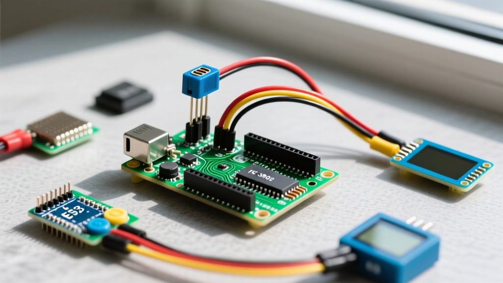

The Challenge of Multi-Peripheral Sensor Integration
Integrating an ultrasonic range detector Arduino module into a simple test circuit is straightforward. However, embedding that same sensor into a complex, multi-peripheral setup—such as an autonomous rover utilizing a 128x64 I2C OLED, a NEMA 17 stepper motor, and a telemetry radio—introduces severe timing and I/O bottlenecks. The standard approach to reading ultrasonic sensors relies on blocking functions that can stall motor controllers and corrupt I2C bus communications. In 2026, as DIY robotics and industrial IoT prototypes demand higher peripheral density, understanding the electrical and programmatic nuances of ultrasonic integration is critical for system stability.
Selecting the Right Ultrasonic Module for Dense Setups
Not all ultrasonic sensors are created equal. When sharing an MCU with high-priority peripherals, the sensor's interface protocol dictates how much processing overhead it will consume. Below is a comparison of the most prevalent modules on the market, evaluated for multi-peripheral viability.
| Module | Interface | Range / Blind Zone | MCU Overhead | 2026 Avg Price |
|---|---|---|---|---|
| HC-SR04 | PWM (Trigger/Echo) | 2cm - 400cm / 2cm | High (Blocking) | $2.50 |
| RCWL-1601 | PWM (Trigger/Echo) | 2cm - 450cm / 2cm | High (Blocking) | $3.20 |
| A02YYUW | UART / I2C | 3cm - 450cm / 3cm | Low (Interrupt/Async) | $18.50 |
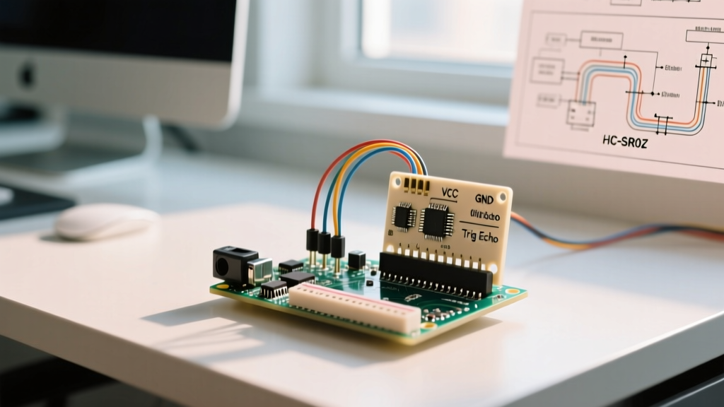
While the HC-SR04 remains the budget king, its reliance on precise microsecond pulse timing makes it a liability in multi-threaded or interrupt-heavy environments. For setups requiring simultaneous OLED rendering and stepper motor acceleration, upgrading to a UART-based sensor like the DFRobot A02YYUW offloads the timing burden to the sensor's internal ASIC, freeing your Arduino's timers for peripheral management.
The Timing Bottleneck: Why pulseIn() Destroys Multi-Tasking
The standard method for reading an HC-SR04 involves the Arduino pulseIn() function. This function halts all MCU operations while waiting for the Echo pin to go HIGH and then back to LOW.
The Physics of the Block: At 20°C, the speed of sound is approximately 343 m/s. A round-trip distance of 1 cm takes about 58.3 µs. If an object is out of range (max 400 cm), the sensor will hold the Echo pin HIGH for roughly 23.3 milliseconds before timing out.
In a multi-peripheral setup, a 23.3 ms blocking delay is catastrophic. If you are using the AccelStepper library to control a NEMA 17 motor, the library requires its run() function to be called at least every 1-2 ms to maintain smooth micro-stepping. A 23 ms block will cause the stepper motor to stall, miss steps, or produce severe acoustic resonance. Furthermore, if your setup includes an I2C OLED display, blocking the main loop prevents the display buffer from updating, resulting in visible tearing or frozen telemetry data.
The Non-Blocking Solution
To integrate an ultrasonic range detector Arduino setup without blocking, you must abandon pulseIn(). Instead, utilize hardware interrupts or a dedicated timer library like NewPing. NewPing utilizes Timer2 to ping the sensor asynchronously, allowing the main loop to continue servicing I2C displays and motor controllers. Alternatively, wire the Echo pin to an external interrupt pin (e.g., Pin 2 or 3 on an Uno) and use an Interrupt Service Routine (ISR) to capture the micros() timestamp on the rising and falling edges, calculating the delta without halting the CPU.
Voltage Translation and GPIO Protection
A frequent failure mode in advanced multi-peripheral builds occurs when migrating from 5V AVR boards (like the Uno or Mega) to 3.3V ARM or ESP32 architectures. The HC-SR04 and RCWL-1601 require a 5V VCC supply to generate sufficient acoustic power, and consequently, their Echo pins output a 5V logic HIGH.
Feeding a 5V signal directly into a 3.3V ESP32 GPIO will eventually degrade the silicon, leading to phantom reads or permanent pin death. You must implement logic level shifting:
- Resistive Divider: A simple voltage divider using a 1kΩ resistor (series) and a 2kΩ resistor (to ground) will drop the 5V Echo signal to a safe ~3.33V. This is cheap but adds slight capacitance, which can blur the rising edge at high frequencies.
- MOSFET Level Shifter: For setups requiring pristine signal edges, use a BSS138 N-channel MOSFET bidirectional level shifter module (typically $1.50). This ensures sub-microsecond edge transitions, preserving the 58 µs/cm accuracy.
Eliminating Acoustic Crosstalk in Sensor Arrays
When your multi-peripheral setup requires spatial awareness—such as a robotic arm needing obstacle avoidance on three axes—using multiple ultrasonic sensors introduces acoustic crosstalk. If two HC-SR04 modules fire simultaneously, Sensor A may read the acoustic bounce from Sensor B's trigger, resulting in phantom obstacles and erratic servo movements.
Sequential Polling vs. Hardware Multiplexing
The software approach is sequential polling: fire Sensor 1, wait 25 ms for the acoustic wave to dissipate, then fire Sensor 2. While safe, polling three sensors sequentially adds a minimum of 75 ms of latency to your control loop.
For high-speed multi-peripheral arrays, hardware multiplexing is superior. By utilizing a PCA9548A I2C Multiplexer or a 74HC4051 analog multiplexer, you can route multiple Echo signals into a single Arduino hardware interrupt pin. This reduces the I/O footprint, allowing you to reserve precious GPIO pins for your SPI TFT displays and motor drivers, while maintaining strict, timer-controlled sequential firing via the multiplexer's control lines.
Real-World Troubleshooting Edge Cases
Even with perfect wiring, environmental factors in multi-sensor setups can cause erratic behavior. Here is how to diagnose specific edge cases:
- Constant 0 cm or 400 cm Reads: Usually indicative of a power brownout. When a peripheral like a high-torque servo or a Wi-Fi radio (ESP8266/ESP32) activates, it can pull the 5V rail down to 4.2V. The HC-SR04's internal oscillator becomes unstable below 4.5V. Fix: Add a 470µF electrolytic capacitor directly across the sensor's VCC and GND pins to buffer transient current draws.
- Thermal Drift in Industrial Enclosures: Ultrasonic sensors calculate distance based on a fixed speed of sound (343 m/s at 20°C). If your multi-peripheral setup is housed in an enclosure where internal components (like motor drivers) raise the ambient temperature to 45°C, the speed of sound increases to ~358 m/s. This introduces a 4% distance error. Fix: Integrate a BME280 I2C temperature/pressure sensor into your setup and apply a dynamic compensation formula to the ultrasonic time-of-flight calculation.
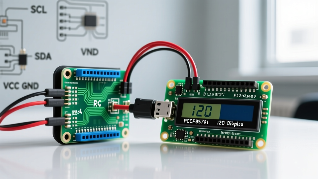
- I2C Bus Lockups: If your ultrasonic sensor's ground loop is shared with a high-current motor driver, ground bounce can inject noise into the I2C SDA/SCL lines, freezing your OLED display. Fix: Implement star-grounding topology and use 4.7kΩ pull-up resistors on the I2C lines, keeping digital sensor grounds isolated from motor power grounds until the main power supply terminal.
Summary
Successfully deploying an ultrasonic range detector Arduino module in a multi-peripheral environment requires moving beyond basic tutorials. By addressing the blocking nature of pulse timing, protecting 3.3V logic from 5V echoes, and mitigating acoustic crossthrough via hardware multiplexing, you ensure that your rangefinding operates seamlessly alongside steppers, displays, and telemetry systems. Invest in UART-based sensors for asynchronous operation, or rigorously manage interrupts and power decoupling if sticking to legacy PWM modules.