
The Multi-Peripheral Bottleneck in Audio Sampling
Integrating an arduino audio sensor into a complex build—such as a smart home voice-activated relay system or an audio-reactive LED matrix—introduces severe timing and signal integrity challenges. When your microcontroller is simultaneously driving an I2C OLED display, toggling PWM pins for servos, and reading an analog microphone, the standard polling methods fail catastrophically. Audio waveforms require strict adherence to the Nyquist-Shannon sampling theorem. If your sampling rate drops or jitters, you introduce aliasing, rendering frequency analysis (like FFT) or envelope detection useless.
In 2026, maker projects rarely rely on a single sensor. A typical smart-environment node might include an SSD1306 display, a 5V relay module, and a WS2812B LED strip alongside the microphone. Updating a 128x64 I2C OLED display via the standard Wire library takes approximately 3.5 to 5 milliseconds. If you are using a blocking analogRead() function inside your main loop, the microcontroller halts all sampling while the I2C bus transmits data. This creates massive gaps in your audio buffer, destroying the phase coherence of the signal. To build a reliable multi-peripheral audio setup, you must fundamentally change how the ATmega328P (or your chosen MCU) handles analog-to-digital conversion.
Selecting the Right Arduino Audio Sensor for Mixed-Signal Builds
Not all audio sensors are created equal, especially when operating in electrically noisy environments shared with inductive loads like relays and stepper motors. Choosing the correct module dictates your hardware filtering requirements and software overhead.
| Sensor Module | Core IC / Component | 2026 Avg. Price | Output Type | Best Use Case |
|---|---|---|---|---|
| Adafruit MAX9814 | MAX9814 Electret Amp | $15.95 | Raw Analog (Waveform) | High-fidelity FFT, voice recognition, multi-peripheral hubs. |
| SparkFun Sound Detector | Custom Op-Amp Network | $13.50 | Envelope, Gate, Audio | Audio-reactive lighting, simple beat detection without heavy DSP. |
| Generic KY-037 | LM393 Comparator | $2.50 | Digital (Threshold) | Basic clap-switches. Avoid for actual waveform sampling. |
For multi-peripheral setups where CPU cycles are at a premium, the SparkFun Sound Detector is highly recommended. Its dedicated "Envelope" output hardware-rectifies and smooths the audio signal, allowing you to sample at a much lower rate (e.g., 50Hz) without missing audio peaks, freeing up the MCU to handle I2C displays and motor control. However, if you need raw waveform data for Fast Fourier Transforms (FFT), the Adafruit MAX9814 is the industry standard, featuring automatic gain control (AGC) that prevents signal clipping when ambient noise levels fluctuate.
Pin Allocation Matrix for Complex Builds
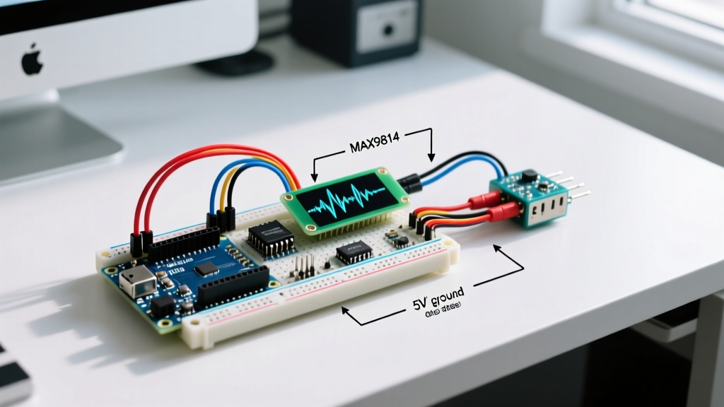
Proper pin allocation is critical to avoid hardware interrupts conflicting with timer-based PWM outputs used for servos and audio sampling. Below is an optimized pinout matrix for an Arduino Uno (ATmega328P) managing a MAX9814, an SSD1306 I2C OLED, a 5V relay, and a standard micro-servo.
| Peripheral | Arduino Uno Pin | Hardware Constraint / Notes |
|---|---|---|
| MAX9814 Audio Out | A0 (ADC0) | Keep away from digital PWM traces to reduce capacitive coupling. |
| SSD1306 OLED (SDA/SCL) | A4 / A5 | I2C Bus. Requires 4.7kΩ pull-up resistors if using long wires. |
| Micro-Servo PWM | D9 | Uses Timer1. Do not use analogWrite() on D9/D10 if using custom Timer1 ISR. |
| 5V Relay Module (IN) | D8 | Active LOW. Use an optocoupler or NPN transistor to isolate MCU from back-EMF. |
Solving the Sampling Rate Crisis: Free-Running ADC
According to the Arduino Analog Pins Documentation, a standard analogRead() takes about 112 microseconds, yielding a maximum theoretical sampling rate of roughly 8.9kHz. In a multi-peripheral loop burdened by display updates, this drops to 2kHz or lower. To capture audio reliably at 20kHz+ while the main loop handles other peripherals, you must configure the ADC into Free-Running Mode utilizing an Interrupt Service Routine (ISR).
Configuring the ATmega328P Registers
By manipulating the ADC Control and Status Registers directly, the hardware automatically triggers the next sample the moment the previous one finishes, completely independent of the main loop() or I2C delays.
- ADCSRA (ADC Control and Status Register A): Enable the ADC, enable the auto-trigger, enable the interrupt, and set the prescaler.
- ADCSRB (ADC Control and Status Register B): Clear the trigger source bits to select Free-Running mode.
Expert Pro-Tip: For voice-band audio (up to 4kHz), a sampling rate of 8kHz is sufficient. Set the ADC prescaler to 128. If you are analyzing music or acoustic anomalies up to 15kHz, you need a 32kHz+ sample rate. Change the prescaler to 32 or 16. Beware: lower prescalers reduce the ADC's effective resolution (dropping from 10-bit down to 8-bit or 7-bit due to internal capacitor charging limits).
Inside the ISR(ADC_vect), you simply read the ADCL and ADCH registers and push the value into a circular ring buffer. The main loop can then read from this buffer whenever it has spare cycles to update the OLED display or trigger a relay, ensuring zero audio samples are dropped regardless of I2C bus congestion.
Grounding and Noise Isolation Strategies
The most frequent cause of failure in multi-peripheral audio setups is ground bounce and power rail sag. When a 5V relay coil energizes or a servo motor stalls, it can draw upwards of 500mA in milliseconds. If the audio sensor shares the same 5V rail and ground return path, the voltage spike induces a massive low-frequency hum (often 50Hz/60Hz mains hum or PWM whine) into the microphone's analog output.
- Star Grounding Topology: Never daisy-chain your grounds. Run a dedicated ground wire from the Arduino's GND pin to the audio sensor, and a separate ground wire from the Arduino's GND to the relay/servo power block. They should only meet at a single "star" point.
- Dedicated Analog LDO: For professional-grade 2026 builds, power the MAX9814 using a dedicated low-dropout regulator (like the LP2985 or HT7333) rather than the Arduino's onboard 5V regulator. This physically isolates the analog power domain from the digital switching noise of the ATmega328P.
- Opto-Isolation for Relays: Always use optocouplers (like the PC817) between the Arduino's digital output pins and the relay module's input pins. This prevents inductive flyback from traveling back through the digital ground plane and corrupting the ADC reference voltage.
Edge Cases and Troubleshooting
1. The I2C Bus Lockup During High-Frequency Interrupts
If your ADC ISR fires every 25 microseconds (40kHz sample rate), and you attempt to use the Wire library to update an OLED, the I2C bus may freeze. The Wire library relies on its own interrupts to handle clock stretching and data acknowledgement. If the ADC ISR monopolizes the CPU, the I2C interrupts are delayed, causing the OLED to hang.
Fix: Keep the ISR as short as possible (only read the register and increment a buffer pointer). Alternatively, temporarily disable the ADC interrupt (ADCSRA &= ~(1 << ADIE);) right before calling Wire.endTransmission(), and re-enable it immediately after.
2. DC Offset Drift in Capacitive Coupling
Audio sensors output a signal centered around a DC bias (usually VCC/2, or 2.5V on a 5V system). In environments with extreme temperature fluctuations, the bias voltage of cheap generic sensors (like the KY-037) can drift, causing the audio waveform to clip against the 0V or 5V rails.
Fix: Implement a software-based DC blocking filter. Calculate a running average of the last 512 samples and subtract this moving average from the incoming raw data. This dynamically centers the waveform at true zero, regardless of hardware thermal drift.
3. Aliasing from PWM Motor Controllers
If you are driving a DC motor via PWM on a pin adjacent to A0 (such as D14/A0 on some clones, or simply routing traces too closely on a custom PCB), the 490Hz or 980Hz PWM switching frequency will bleed into the analog trace.
Fix: Add a simple hardware RC low-pass filter (a 10kΩ resistor and a 10nF ceramic capacitor) at the output of the audio sensor before it enters the Arduino's A0 pin. This sets the cutoff frequency around 1.5kHz, effectively stripping out high-frequency digital switching noise before it reaches the ADC sample-and-hold circuit.