
The Physics of Tachometry: Why Sensor Choice Matters
Measuring the rotational speed of a motor, wheel, or shaft is a foundational skill in robotics and automation. When building a tachometer, the term arduino rpm sensor usually refers to one of two underlying technologies: optical interruption or magnetic Hall effect sensing. For beginners, the LM393 slotted optical sensor module is the undisputed starting point. It offers digital output, simple threshold adjustment, and requires no complex analog-to-digital conversion. However, successfully reading high-speed rotations requires moving beyond basic polling loops and embracing hardware interrupts.
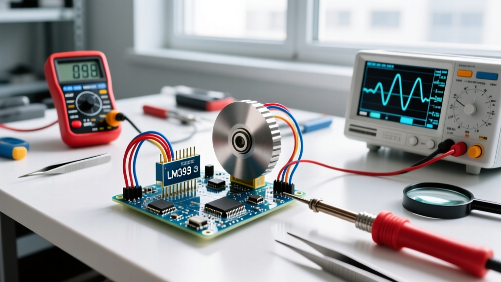
In this comprehensive 2026 guide, we will interface the widely available LM393 optical speed sensor module with an Arduino Uno R4 Minima. We will cover the exact wiring, provide production-ready C++ code using microsecond timing, and explore the real-world edge cases that cause RPM readings to fluctuate or fail entirely.
Optical vs. Magnetic: Selecting the Right Sensor
Before wiring anything, it is crucial to understand the physical limitations of your sensor type. Optical sensors rely on an infrared (IR) beam breaking across a physical gap, while magnetic sensors detect changes in magnetic flux. Here is how the most common hobbyist modules compare in real-world applications:
| Feature | LM393 Slotted Optical (IR) | A3144 Hall Effect (Magnetic) | TCRT5000 Reflective Optical |
|---|---|---|---|
| Detection Method | Beam interruption via slotted disc | Magnetic field polarity shift | IR light bouncing off a target |
| Max Reliable RPM | ~15,000 RPM (with 20-slot disc) | ~10,000 RPM (limited by magnet size) | ~5,000 RPM (surface dependent) |
| Environmental Weakness | Ambient sunlight / high-intensity IR | Stray electromagnetic fields (EMI) | Dust, oil, and reflective shafts |
| Typical 2026 Cost | $2.50 (pack of 5) | $3.00 (pack of 10) | $1.80 (per unit) |
2026 Hardware Bill of Materials (BOM)
To build a robust, high-resolution tachometer, you will need the following components. Prices reflect early 2026 market averages from major electronics distributors:
- Microcontroller: Arduino Uno R4 Minima ($20.00) - Chosen for its Renesas RA4M1 ARM Cortex-M4 processor, which handles high-frequency interrupts far better than the legacy ATmega328P.
- Sensor: LM393 IR Slotted Optical Speed Sensor Module ($2.50).
- Encoder Disc: 20-slot acrylic or metal interrupter wheel ($1.50).
- Wiring: Silicone-stranded jumper wires (female-to-female) ($4.00).
- Power Supply: 5V 2A USB-C PD adapter to ensure clean voltage rails ($8.00).
Wiring the LM393 to the Arduino Uno R4
The LM393 module typically features four pins: VCC, GND, DO (Digital Output), and AO (Analog Output). For RPM counting, we exclusively use the Digital Output pin, which triggers LOW when the IR beam is broken and HIGH when it is clear. The onboard potentiometer adjusts the ambient light threshold, but we rely on the digital comparator for clean square waves.
Pinout Configuration
- VCC → Arduino 5V (Do not use 3.3V; the LM393 comparator requires a minimum of 3.0V, but 5V ensures a sharp logic HIGH threshold).
- GND → Arduino GND.
- DO → Arduino Pin 2. (Pin 2 is tied to hardware interrupt 0 on the Uno architecture. Using standard digital pins with
digitalRead()in the main loop will result in missed pulses at high RPMs).
Note: Leave the AO (Analog Output) pin disconnected. Reading analog values introduces a ~100μs delay per read, which is catastrophic for high-speed tachometry.
The Code: Hardware Interrupts and Microsecond Timing
The most common mistake beginners make when coding an arduino rpm sensor is using millis() or counting pulses over a fixed one-second window. Both methods introduce massive quantization errors at high speeds. Instead, we measure the exact time between individual pulses using micros() and hardware interrupts.
According to the official Arduino attachInterrupt() Documentation, executing an Interrupt Service Routine (ISR) pauses the main program, ensuring no pulses are missed even if the microcontroller is busy driving a display or PID loop.
volatile unsigned long pulseStartTime = 0;
volatile unsigned long pulseDuration = 0;
volatile bool pulseReceived = false;

const int sensorPin = 2; // Hardware interrupt pin
const int slots = 20;    // Number of slots on the encoder disc
const unsigned long timeout = 1000000; // 1 second in microseconds

void setup() {
  Serial.begin(115200);
  pinMode(sensorPin, INPUT_PULLUP); // Pull-up prevents floating noise
  // Trigger on FALLING edge (beam breaks)
  attachInterrupt(digitalPinToInterrupt(sensorPin), pulseISR, FALLING);
  pulseStartTime = micros();
}

void loop() {
  if (pulseReceived) {
    noInterrupts(); // Safely copy volatile variables
    unsigned long duration = pulseDuration;
    pulseReceived = false;
    interrupts();

    // RPM = (60 seconds * 1,000,000 microseconds) / (duration * slots)
    float rpm = 60000000.0 / (float)(duration * slots);
    Serial.print('RPM: ');
    Serial.println(rpm, 1);
  }
  else if (micros() - pulseStartTime > timeout) {
    // Motor has stalled or stopped spinning
    Serial.println('RPM: 0.0 (Stalled)');
    delay(500); // Prevent serial flooding
  }
  delay(50); // Throttle serial output for readability
}

void pulseISR() {
  unsigned long currentTime = micros();
  pulseDuration = currentTime - pulseStartTime;
  pulseStartTime = currentTime;
  pulseReceived = true;
}
Why micros() Instead of millis()?
Let us break down the math. If a motor is spinning at 6,000 RPM with a 20-slot disc, it generates 2,000 pulses per second. That means one pulse occurs every 0.5 milliseconds (500μs). The millis() function only updates every ~1ms. If you use millis(), your time delta will alternate between 0 and 1, resulting in RPM calculations that wildly swing between 0 and infinity. The micros() function resolves down to 4μs on the Uno R4, providing a highly stable time delta for accurate velocity calculations.
Real-World Calibration and Edge Cases
Theoretical code often fails when exposed to physical realities. As detailed in the Texas Instruments LM393 Datasheet, the comparator's response time is roughly 1.3μs, which is plenty fast. The bottleneck is almost always optical physics and mechanical alignment.
The 'Black Tape' Trick: If you are measuring a bare metal shaft without a slotted disc, you must wrap a piece of black electrical tape around half the shaft's circumference and paint the other half with white-out or reflective paint. Bare aluminum or steel shafts scatter IR light unpredictably, causing the LM393 to trigger multiple false interrupts per rotation. Black electrical tape absorbs 99% of the IR spectrum, ensuring a crisp HIGH-to-LOW transition.
Handling Ambient IR Interference
The LM393 module uses unmodulated infrared LEDs. This makes it highly susceptible to ambient sunlight, which contains massive amounts of IR radiation. If your robot or motor is operating outdoors or near a south-facing window, the receiver phototransistor will become saturated, and the digital output will lock HIGH. The Fix: 3D print a small, opaque shroud (using black PLA or PETG) that slips over the sensor U-channel. This physical light baffle is mandatory for any outdoor or brightly lit environment deployment.
Troubleshooting Signal Bounce and Dropouts
Even with perfect code, you may notice the RPM reading jittering by 5-10% at steady speeds. This is usually caused by mechanical 'wobble' or electrical switch bounce. Follow this diagnostic checklist:
- Check the Potentiometer: Use a small Phillips screwdriver to adjust the blue potentiometer on the LM393 module. While the motor is spinning, turn the pot until the onboard LED flickers perfectly in sync. If it is too sensitive, it will trigger on dust particles; if too dull, it will miss the trailing edge of the slot.
- Implement Software Debouncing: If the physical edges of your slotted disc are rough, the IR beam might 'chatter' as it crosses the threshold. Add a simple software debounce in the ISR: ignore any pulse that arrives less than 50μs after the previous one.
- Hardware RC Filter: For extreme EMI environments (like near large brushed DC motors), solder a 0.1μF ceramic capacitor between the DO pin and GND directly on the sensor module. This creates a low-pass filter that smooths out high-frequency electrical noise before it reaches the Arduino's interrupt pin. For deeper insights into signal conditioning, refer to the SparkFun Interrupts Tutorial.
- Verify Power Rails: Motors induce severe back-EMF. Never power the motor and the Arduino from the exact same unregulated battery pack without a flyback diode and an opto-isolator. Voltage sags caused by motor startup will brown-out the LM393, resetting its comparator state and causing phantom RPM spikes.
Summary
Interfacing an arduino rpm sensor is a rite of passage for embedded systems engineers. By abandoning polling loops in favor of hardware interrupts, utilizing microsecond timing, and respecting the optical limitations of the LM393 module, you can build a tachometer that rivals commercial industrial equipment. Always remember that in sensor integration, the physical mounting and light isolation are just as critical as the C++ code running on the silicon.