
The Breadboard Illusion vs. Field Reality
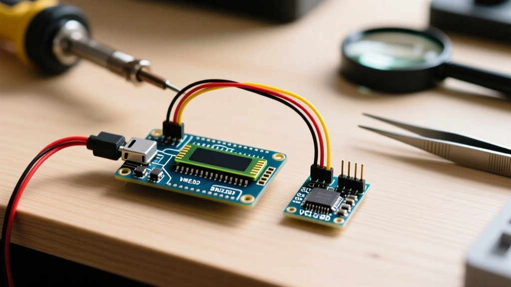
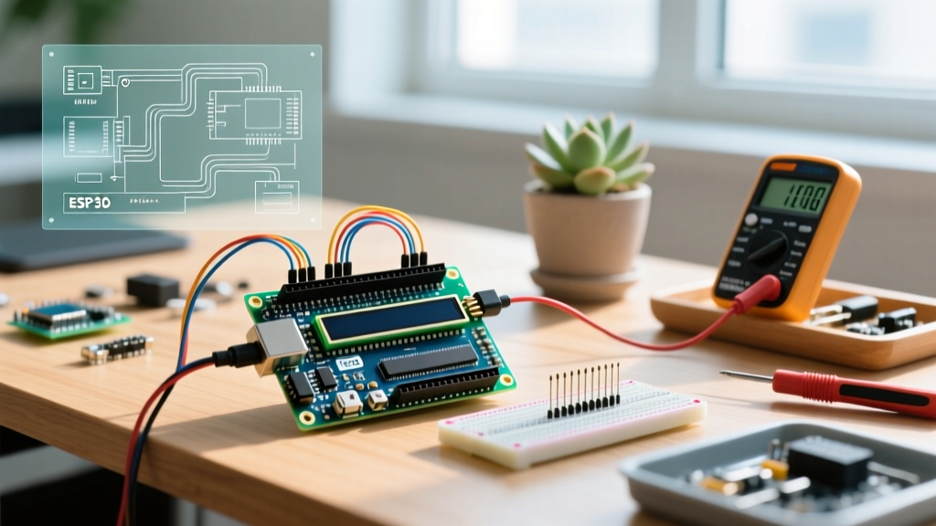
Search for any basic lcd arduino display tutorial, and you will inevitably find a breadboard wired with 16 jumper cables connecting a parallel HD44780 display to a microcontroller. While this works perfectly on a quiet desk, it is a catastrophic failure point in real-world applications. In environments like automated greenhouses, industrial pump stations, or outdoor weather monitors, electromagnetic interference (EMI) and mechanical vibration will quickly cause parallel data lines to drop bits, resulting in garbled text or complete bus lockups.
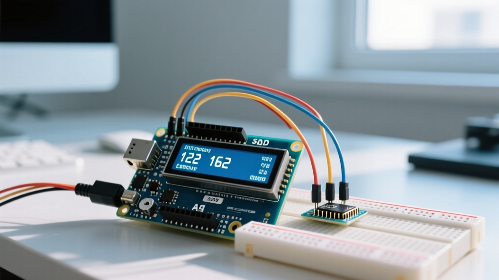
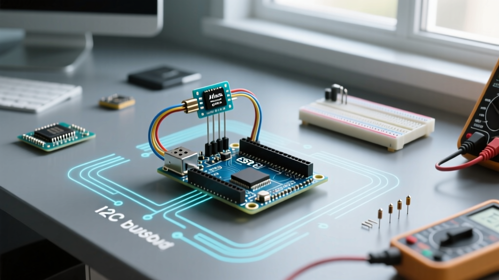
For robust, field-deployable projects in 2026, the standard is an I2C-backed LCD module. By shifting from a 16-wire parallel interface to a 4-wire I2C serial connection (SDA, SCL, VCC, GND), we drastically reduce wiring complexity and improve noise immunity. This guide details the exact hardware selection, EMI hardening, and firmware implementation required to build a reliable 20x4 environmental monitoring dashboard.
Bill of Materials (BOM) & Component Selection
To ensure long-term reliability, we must move beyond generic, unbranded kits. Here is the precise BOM for a professional-grade display node:
- Microcontroller: Arduino Uno R4 Minima (~$20.00). The R4 Minima features a Renesas RA4M1 ARM Cortex-M4 processor with native, hardware-accelerated I2C that is far less prone to software-induced bus lockups than the legacy ATmega328P found in the Uno R3.
- Display Module: 20x4 Character LCD with HD44780 Controller and PCF8574T I2C Backpack (~$4.50 - $6.00 via DigiKey or Mouser). Ensure the backpack uses the PCF8574T, not the PCF8574AT, to avoid address conflicts if you plan to add multiple sensors later.
- Pull-Up Resistors: 4.7kΩ 1/4W Metal Film Resistors (x2) (~$0.10).
- Decoupling Capacitors: 100nF (0.1µF) MLCC Ceramic and 10µF Electrolytic (~$0.25).
- Power Supply: 5V 2A Buck Converter (e.g., LM2596 module) to drive the backlight independently of the MCU's linear regulator.
The I2C Addressing Headache: PCF8574 vs. PCF8574A
The number one reason developers abandon an lcd arduino display project during prototyping is an I2C address mismatch. The I2C backpacks soldered onto the back of these LCDs utilize an I/O expander chip. Depending on the exact manufacturer batch, this chip is either a PCF8574 or a PCF8574A. They have different hardcoded base addresses.
| Expander Chip | Base Address (Hex) | Address with A0, A1, A2 Jumpers Open | Common Use Case |
|---|---|---|---|
| PCF8574 | 0x20 | 0x27 | Standard generic 1602/2004 LCD backpacks |
| PCF8574A | 0x38 | 0x3F | Alternative batch backpacks, often used to avoid conflicts |
Pro-Tip: Never guess the address. Always run an I2C Scanner sketch via the Arduino IDE before integrating the display into your main firmware. If your serial monitor returns 0x3F but your code initializes with 0x27, the display will remain completely blank, leading hours of misdirected troubleshooting.
Hardware Integration & EMI Hardening
In a real-world greenhouse, turning on a 120V AC water pump via a relay module generates massive inductive voltage spikes. These spikes couple into low-voltage I2C lines, corrupting data packets. To prevent the LiquidCrystal_I2C library from hanging when the I2C bus experiences a corrupted clock pulse, you must physically harden the bus.
1. Mandatory Pull-Up Resistors
The Arduino Uno R4 Minima has internal pull-up resistors, but they are typically 20kΩ to 50kΩ—far too weak for a noisy environment. According to the Texas Instruments Application Note SLVA689 on I2C bus pull-up resistor calculation, a 4.7kΩ external pull-up resistor on both the SDA and SCL lines provides the optimal balance between rise-time speed and current sinking capability for a standard 100kHz I2C bus. Solder these directly between the 5V line and the SDA/SCL pins at the LCD backpack.
2. Local Decoupling
The LED backlight on a 20x4 LCD draws between 80mA and 120mA. When the backlight turns on, it creates a localized voltage sag on the 5V rail. If the logic chip (HD44780) experiences this sag, it will reset mid-character, resulting in "ghosting" or shifted text. Solder a 100nF ceramic capacitor and a 10µF electrolytic capacitor directly across the VCC and GND pins on the back of the I2C backpack. This creates a local energy reservoir that absorbs high-frequency switching noise.
3. Cable Length Limitations
I2C was designed for on-board communication, not long-distance runs. The total bus capacitance must not exceed 400pF. Using standard 22 AWG silicone wire, you are limited to approximately 30cm (12 inches) of cable length between the Arduino and the LCD. If your environmental monitor requires the display to be mounted further away, you must use an I2C bus extender IC like the P82B715, which converts the signal to a differential pair capable of running up to 30 meters over standard CAT5e cable.
Power Management: Protecting the MCU Regulator
A common mistake in real-world deployments is powering the LCD backlight directly from the Arduino's 5V pin while the board is powered via the VIN barrel jack (e.g., a 9V or 12V wall adapter). The Arduino's onboard linear regulator must dissipate the excess voltage as heat. Powering a 120mA LCD backlight from a 12V source forces the regulator to dissipate nearly 1 Watt of heat, which will trigger thermal shutdown in enclosed project boxes.
The Solution: Use a dedicated 5V buck converter to step down your main 12V supply. Wire the 5V output directly to the LCD's VCC and the Arduino's 5V pin (bypassing the onboard regulator entirely). This ensures the display remains bright and the microcontroller stays cool, even in 40°C (104°F) ambient greenhouse conditions.
Firmware Initialization & Custom Characters
When initializing the display in your Arduino sketch, timing is critical. The HD44780 controller requires a specific power-on sequence. The LiquidCrystal_I2C library handles this, but you must include a minimum 50ms delay in your setup() function before calling lcd.begin(20, 4) to allow the LCD's internal voltage multiplier to stabilize.
Expert Insight: To make your environmental monitor look professional, utilize the HD44780's Custom Character Generator RAM (CGRAM). You can define up to eight 5x8 pixel custom characters. This is perfect for creating dedicated icons for soil moisture drops, temperature thermometers, or Wi-Fi signal bars, freeing up standard ASCII characters for your actual data readings.
#include <Wire.h>
#include <LiquidCrystal_I2C.h>

// Initialize with correct address, columns, and rows
LiquidCrystal_I2C lcd(0x27, 20, 4);

// Custom thermometer character
byte thermometer[8] = {
  B00100,
  B01010,
  B01010,
  B01010,
  B01110,
  B11111,
  B11111,
  B01110
};

void setup() {
  delay(50); // Allow LCD voltage multiplier to stabilize
  lcd.init();
  lcd.backlight();
  lcd.createChar(0, thermometer);
  lcd.setCursor(0, 0);
  lcd.write((byte)0); // Print custom thermometer
  lcd.print(" Soil Temp: 24.5C");
}

void loop() {
  // Update sensor data here
}
Real-World Troubleshooting Matrix
When deploying your lcd arduino display in the field, use this diagnostic matrix to quickly identify and resolve common anomalies:
| Symptom | Root Cause | Field Fix |
|---|---|---|
| Top row shows solid black boxes | Contrast trimpot is misadjusted, or LCD initialized in 8-bit mode instead of 4-bit. | Turn the 10kΩ Bourns trimpot on the backpack counter-clockwise until characters appear. Verify lcd.begin() parameters. |
| Display works, but freezes when relays click | EMI spike corrupts I2C clock line, causing SDA to latch LOW. | Install 4.7kΩ external pull-ups. Add a software watchdog timer (WDT) to reset the MCU if the I2C bus hangs for >2 seconds. |
| Characters shift randomly to the right | Voltage sag on the 5V rail causing the HD44780 to lose its DDRAM cursor position. | Add local 100nF/10µF decoupling capacitors to the LCD VCC/GND pins. Power the backlight via a separate buck converter. |
| Flickering backlight | PWM interference or insufficient current from the Arduino 5V pin. | Ensure the backpack jumper (if present) is closed to enable continuous backlight, or drive the LED pin with a dedicated MOSFET. |
Conclusion
Transitioning from a fragile breadboard prototype to a hardened, field-ready environmental monitor requires respecting the physical limitations of the I2C protocol and the HD44780 controller. By selecting the correct PCF8574T backpack, implementing proper 4.7kΩ pull-up resistors, managing local power decoupling, and utilizing custom CGRAM characters, your lcd arduino display will survive the harsh electrical noise and temperature fluctuations of real-world deployment. Build it right the first time, and you will eliminate the most common point of failure in DIY sensor networks.