
Mastering Precision Motion: Arduino with Stepper Motor Driver Integration
Integrating an Arduino with stepper motor driver modules is the foundational skill for building CNC routers, 3D printers, and automated camera sliders. Unlike standard DC motors, stepper motors move in discrete increments, allowing for sub-millimeter positional accuracy. However, an Arduino's GPIO pins cannot supply the current or voltage required to drive these motors directly. This is where dedicated chopper drivers like the A4988 and DRV8825 come into play.
In this comprehensive 2026 wiring and code guide, we will cover the exact hardware specifications, the critical Vref current-limiting calibration, microstepping configurations, and non-blocking code implementation using the AccelStepper library.
Hardware Selection and 2026 Market Pricing
Before wiring, you must select the right components. While clone boards flood the market, understanding the difference between genuine and cloned silicon is vital for thermal reliability.
- Microcontroller: Arduino Uno R4 Minima (~$28). The R4's 48MHz Cortex-M4 processor handles complex kinematic calculations far better than the legacy R3.
- Stepper Motor: NEMA 17 (e.g., 17HS4401S). Rated at 1.5A to 1.7A per phase, 59 N·cm holding torque (~$14 - $18).
- Driver Modules: A4988 or DRV8825 carrier boards. Genuine Pololu A4988 carriers cost around $8.50, while generic clones range from $2.00 to $3.50. Clones often use inferior sense resistors and counterfeit chips that overheat at 1.2A.
- Power Supply: 12V 5A (60W) Switching PSU. Steppers draw maximum current at low speeds and stall; ensure your PSU can handle the continuous amperage.
- Decoupling Capacitor: 100µF 25V Low-ESR Electrolytic Capacitor. Never skip this component.
A4988 vs. DRV8825: Which Driver Should You Use?
Both drivers share the exact same pinout and form factor, but their internal silicon differs. According to the Texas Instruments DRV8825 Datasheet, the DRV8825 supports finer microstepping and slightly higher current limits, but it is more susceptible to voltage spikes.
| Feature | A4988 (Allegro) | DRV8825 (TI) |
|---|---|---|
| Max Continuous Current | 1.5A (with heatsink) | 1.5A (with heatsink) |
| Max Peak Current | 2.0A | 2.5A |
| Microstepping Resolution | Up to 1/16 step | Up to 1/32 step |
| Current Sense Resistor (Rs) | Typically 0.05Ω or 0.1Ω | Typically 0.1Ω |
| Minimum Voltage Spike Rating | 35V | 45V |
Step-by-Step Wiring Diagram and Pinout
Wiring an Arduino with stepper motor driver modules requires separating the logic voltage (VDD) from the motor voltage (VMOT). The A4988/DRV8825 breakout boards have two distinct ground planes that are tied together on the PCB, but you must route power correctly.
Power and Logic Connections
- VDD & GND (Logic): Connect to the Arduino's 5V and GND pins. This powers the internal logic gates and optocouplers.
- VMOT & GND (Motor): Connect to the 12V PSU positive and negative terminals. Crucial: Solder or plug the 100µF capacitor directly across VMOT and GND as close to the board as possible. This absorbs inductive voltage spikes that will otherwise destroy the driver IC.
- STEP Pin: Connect to Arduino Digital Pin 3. Each rising edge pulses the motor one step.
- DIR Pin: Connect to Arduino Digital Pin 2. HIGH = Clockwise, LOW = Counter-Clockwise.
- ENABLE Pin: Connect to Arduino Digital Pin 8 (Active LOW). Leave floating to default to enabled, or pull LOW via GPIO.
Motor Coil Wiring (The 4-Wire Dilemma)
NEMA 17 motors have two coils (A and B), resulting in 4 wires. You must pair them correctly. If you wire Coil A to 1A and Coil B to 2A, the motor will vibrate violently without rotating. Use a multimeter in continuity mode: wires that show low resistance (typically 1.5Ω to 3.0Ω) belong to the same coil. Connect Coil A to 1A and 1B, and Coil B to 2A and 2B. Polarity within the same coil does not matter for basic operation; swapping 1A and 1B simply reverses the motor's direction.
The Most Critical Step: Setting the Vref Current Limit
The most common failure mode for beginners is skipping the Vref calibration, resulting in melted driver chips or skipped steps. You must adjust the small brass potentiometer on the driver board to limit the current to your motor's rated maximum.
Warning: Never adjust the potentiometer while the logic power (VDD) is disconnected. The chip needs 5V logic to read the reference voltage accurately.
Calculating Vref
The formula depends on the driver IC and the sense resistor (Rs) value printed on the board.
- A4988 Formula:
Vref = Imax × 8 × Rs - DRV8825 Formula:
Vref = Imax × 5 × Rs
Example for a 1.5A NEMA 17 motor using a DRV8825 with a 0.1Ω sense resistor:
Vref = 1.5A × 5 × 0.1Ω = 0.75V.
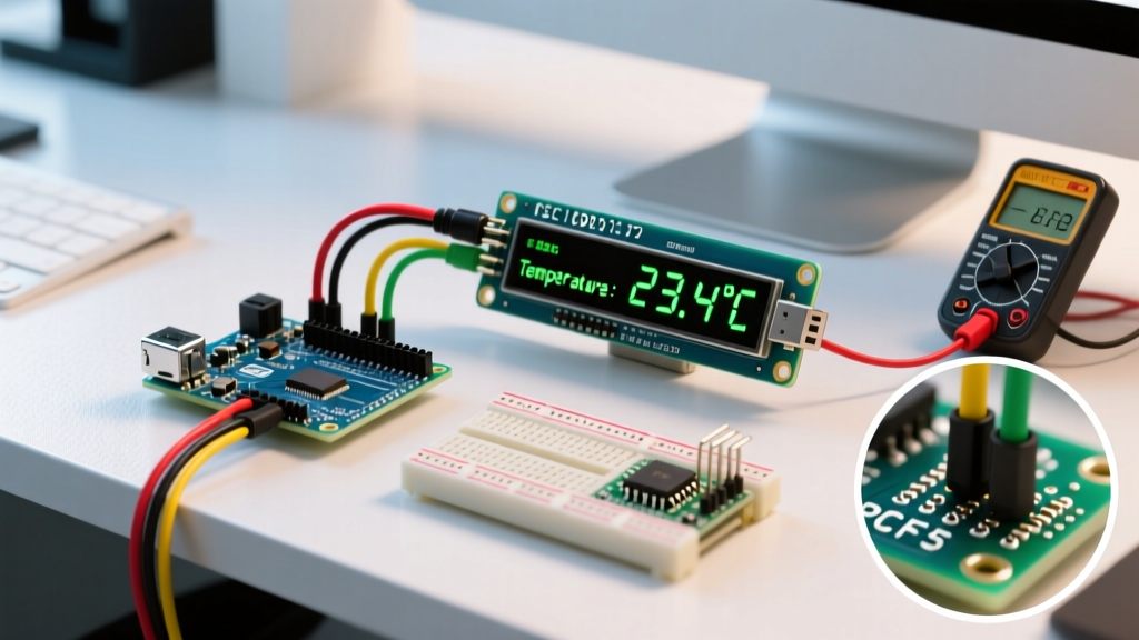
Connect your multimeter's black probe to the Arduino GND and the red probe to the metal shaft of the potentiometer. Use a ceramic screwdriver to turn the pot clockwise to increase voltage, and counter-clockwise to decrease it. Set it exactly to your calculated Vref.
Microstepping Resolution Configuration
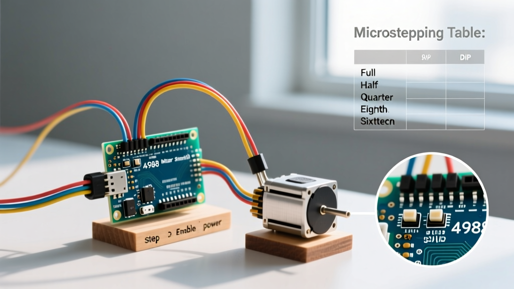
Microstepping divides a full step (usually 1.8°, or 200 steps/rev) into smaller fractions, resulting in smoother motion and less low-speed resonance. You configure this by pulling the MS1, MS2, and MS3 pins HIGH (connected to VDD) or LOW (connected to GND).
| Resolution | MS1 | MS2 | MS3 | Steps per Revolution (1.8° Motor) |
|---|---|---|---|---|
| Full Step | LOW | LOW | LOW | 200 |
| 1/2 Step | HIGH | LOW | LOW | 400 |
| 1/4 Step | LOW | HIGH | LOW | 800 |
| 1/8 Step | HIGH | HIGH | LOW | 1600 |
| 1/16 Step (A4988) | HIGH | HIGH | HIGH | 3200 |
| 1/32 Step (DRV8825) | HIGH | HIGH | HIGH | 6400 |
Pro-Tip: For 3D printers and CNCs, 1/16 microstepping is the industry standard. It provides the best balance between torque consistency and MCU step-pulse limitations.
Non-Blocking Code with AccelStepper
While the default Arduino Stepper.h library works for basic tests, it uses blocking delay() functions that freeze your entire sketch. For real-world applications, we use the AccelStepper Library, which handles acceleration profiles and non-blocking step generation.
Installation and Setup
Install 'AccelStepper' by Mike McCauley via the Arduino Library Manager. Below is the optimized code for a 1/16 microstepped NEMA 17 motor.
#include <AccelStepper.h>

// Define pins
#define stepPin 3
#define dirPin 2
#define enablePin 8

// Interface type 1 means external STEP/DIR driver
AccelStepper stepper(1, stepPin, dirPin);

void setup() {
  pinMode(enablePin, OUTPUT);
  digitalWrite(enablePin, LOW); // Enable driver (Active LOW)

  // Configure AccelStepper parameters
  stepper.setMaxSpeed(1600);      // 1 rev/sec at 1/16 microstepping (3200 steps/rev)
  stepper.setAcceleration(800);   // Smooth ramp up (0.5 sec to max speed)

  // Move exactly 2 full revolutions (6400 steps)
  stepper.moveTo(6400);
}

void loop() {
  // run() must be called continuously for non-blocking acceleration
  if (stepper.distanceToGo() != 0) {
    stepper.run();
  } else {
    // Optional: Disable driver when stationary to save power and reduce heat
    // digitalWrite(enablePin, HIGH);
  }
}
Understanding the Kinematics
In the code above, setMaxSpeed(1600) limits the motor to 1600 steps per second. Because we are using 1/16 microstepping (3200 steps per revolution), the motor will max out at exactly 0.5 Revolutions Per Second (30 RPM). The setAcceleration(800) value dictates how many steps per second, per second, the motor gains. This prevents the rotor from stalling due to inertia during startup.
Troubleshooting Common Failure Modes
Even with perfect wiring, environmental and electrical factors can cause erratic behavior. Here is how to diagnose the most common issues:
- Motor Vibrates but Doesn't Turn: Your step pulse frequency is too high for the motor's torque curve, or the acceleration is too aggressive. Lower
setMaxSpeed()andsetAcceleration()by 50%. Alternatively, check your coil pairing with a multimeter. - Driver Overheating and Shutting Down: The A4988 and DRV8825 have internal thermal shutdown at ~165°C. If the chip is too hot to touch (>60°C), your Vref is set too high, or you lack active cooling. Mount a 40mm 12V fan directly over the heatsinks.
- Erratic Jittering at Low Speeds: This is mechanical resonance, common in full-step and half-step modes. Switch to 1/16 microstepping via the MS pins to smooth out the current sine wave delivered to the coils.
- Missed Steps Under Load: Stepper motors lose torque exponentially as speed increases due to coil inductance and back-EMF. If you need high-speed torque, upgrade from a 12V PSU to a 24V PSU. The driver will chop the 24V down, but the higher voltage forces current through the inductive coils much faster, vastly improving high-RPM torque.
By meticulously calculating your Vref, utilizing low-ESR decoupling capacitors, and leveraging non-blocking acceleration libraries, your Arduino with stepper motor driver setup will achieve the reliability required for professional-grade automation and robotics.