
Beyond the Basic Blink: Integrating an Arduino LCD in Complex Systems
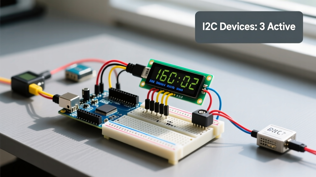
Connecting a standard 16x2 display to a microcontroller is a rite of passage for any maker. However, the real challenge emerges when you attempt to integrate an Arduino LCD into a multi-peripheral setup. When your breadboard is already crowded with a BME688 environmental sensor, a MicroSD data-logging module, and a DS3231 real-time clock, simply plugging in a display often leads to bus collisions, voltage sags, and memory overflows.
In 2026, while 32-bit ARM boards have become more accessible, the 8-bit ATmega328P architecture remains a staple for low-power remote sensor nodes. Successfully running an LCD alongside multiple sensors requires a deep understanding of I2C bus capacitance, strict power budgeting, and strategic pin allocation. This guide details the exact engineering steps required to stabilize an Arduino LCD in a dense multi-peripheral environment.
The I2C Address Collision Matrix
Most modern Arduino LCD setups utilize a 16x2 or 20x4 HD44780-compatible display paired with a PCF8574 I2C backpack. This reduces the wiring from 16 parallel pins down to just four (VCC, GND, SDA, SCL). However, this convenience introduces the risk of I2C address collisions.
The PCF8574 backpacks generally come in two silicon variants, which dictate their base I2C address. If your real-time clock or sensor shares this address, the bus will lock up.
| Backpack IC Variant | Base I2C Address | Common Conflicting Peripherals | Hardware Fix |
|---|---|---|---|
| PCF8574T | 0x27 | Many generic I2C OLEDs, some relay modules | Solder bridge A0-A2 pads to shift up to 0x2F |
| PCF8574AT | 0x3F | DS3231 RTC (0x68 is safe, but 0x3F can clash with specific ADCs) | Use as secondary display or shift down to 0x38 |
If you are deploying multiple sensors that cannot be re-addressed, or if you need to drive two LCDs for a dual-zone monitoring dashboard, you must introduce a TCA9548A I2C Multiplexer (typically $3.50 to $5.00). The TCA9548A allows you to route the I2C bus to 8 separate channels, completely isolating the Arduino LCD from sensitive environmental sensors that might suffer from digital noise injection.
Power Budgeting: The Hidden Cause of LCD Flickering
A frequent failure mode in multi-peripheral setups is the LCD backlight flickering or the display showing garbled blocks during specific operations, such as writing to an SPI MicroSD card. This is rarely a software bug; it is almost always a voltage sag on the 5V rail.
Calculating the 5V Rail Limit
When powering an Arduino Uno or Nano via the USB port, the onboard polyfuse limits the total available current to approximately 400mA. Consider the power draw of a dense sensor node:
- ATmega328P & USB UART: ~50mA
- Arduino LCD Backlight (Standard 100Ω resistor): ~120mA
- MicroSD Module (Active Write): ~150mA
- BME688 & RTC: ~15mA
Total peak draw approaches 335mA. If you add a Wi-Fi module (like an ESP-01 drawing 170mA during transmission), you will instantly trip the USB polyfuse or cause the 5V regulator to brownout, corrupting the LCD controller's internal RAM.
Pro-Tip: Backlight Current Reduction
You can safely reduce the Arduino LCD backlight current draw from 120mA to roughly 40mA without a noticeable drop in indoor visibility. Locate the surface-mount current-limiting resistor on the back of the I2C backpack (usually marked '101' for 100 ohms). Desolder it and replace it with a 330 ohm SMD resistor or wire a through-hole 330 ohm resistor across the VCC and LED jumper pins.
Logic Level Translation in Mixed-Voltage Buses
As of 2026, the vast majority of high-precision environmental sensors (like the Bosch BME688 or Sensirion SHT45) operate strictly at 3.3V. The Arduino LCD and its PCF8574 backpack, however, require 5V to drive the liquid crystal matrix properly.
If you connect a 3.3V sensor and a 5V LCD to the same I2C lines (A4/A5 on an Uno), the 5V pull-up resistors on the LCD backpack will feed 5V logic into the 3.3V sensor's SDA pin, potentially destroying the sensor over time.
The Bidirectional Logic Level Shifter Solution
To safely integrate an Arduino LCD with 3.3V peripherals, you must use a bidirectional logic level converter, such as the TXS0108E or a standard MOSFET-based 4-channel shifter (e.g., BSS138).
- Connect the Low Voltage (LV) side of the shifter to the Arduino 3.3V pin and the 3.3V sensor SDA/SCL.
- Connect the High Voltage (HV) side to the Arduino 5V pin and the Arduino LCD backpack SDA/SCL.
- Ensure both sides share a common ground.
According to the NXP I2C-bus Specification, proper pull-up resistor sizing is critical when adding capacitance via level shifters. Use 4.7kΩ pull-ups on the 5V side and 2.2kΩ on the 3.3V side to maintain sharp signal edges and prevent data corruption.
Software Optimization: Escaping the SRAM Trap
The ATmega328P possesses a mere 2,048 bytes of SRAM. When your code initializes an SD card library, a sensor driver, and a display buffer simultaneously, memory exhaustion leads to silent reboots and erratic behavior.
Many legacy tutorials recommend the standard LiquidCrystal_I2C library. However, this library is outdated, poorly maintained, and allocates memory inefficiently. For multi-peripheral setups, you should exclusively use the hd44780 library by Bill Perry.
Why hd44780 is Superior for Complex Nodes
- Auto-Discovery: It automatically scans the I2C bus to find the LCD address and pin mapping, eliminating the need for hardcoded I2C scanner scripts.
- SRAM Efficiency: It utilizes direct I/O and avoids redundant buffer allocations, saving up to 150 bytes of SRAM compared to older forks.
- Bus Recovery: If a noisy multi-peripheral environment causes an I2C bus lockup, the hd44780 library includes built-in timeout and bus-clearing routines, a feature documented in the official Arduino Wire Library guidelines for advanced I2C management.
Step-by-Step Wiring: LCD + SPI SD + I2C Sensor
To avoid pin conflicts, map your peripherals strictly according to the hardware SPI and I2C buses, leaving analog pins free for sensor inputs.
| Peripheral | Protocol | Arduino Uno/Nano Pins | Notes |
|---|---|---|---|
| Arduino LCD (I2C) | I2C | A4 (SDA), A5 (SCL) | Route through logic shifter if mixed with 3.3V |
| MicroSD Module | SPI | D11 (MOSI), D12 (MISO), D13 (SCK), D10 (CS) | Ensure CS pin is set HIGH when not writing |
| BME688 Sensor | I2C | A4 (SDA), A5 (SCL) | Connect to LV side of level shifter |
Real-World Troubleshooting & Edge Cases
Even with perfect wiring, dense setups present unique edge cases. Here is how to diagnose the most common multi-peripheral LCD failures:
1. Display Freezes During SD Card Initialization
The SD library defaults to a slow SPI clock speed during initialization, which can monopolize the microcontroller's interrupt vector. If your LCD update routine relies on timers, the display will freeze. Fix: Initialize the SD card in your setup() function before initializing the LCD, and ensure you are not calling SD write functions inside hardware interrupt service routines (ISRs).
2. Ghosting or Faded Characters
If the LCD shows faint, unreadable text, the contrast potentiometer on the back of the backpack may be misadjusted. However, in multi-peripheral setups, ghosting often indicates a ground loop or insufficient current return path. Fix: Run a dedicated ground wire from the LCD backpack directly to the Arduino's GND pin, rather than daisy-chaining the ground through a breadboard shared with high-current SPI modules.
3. I2C Bus Timeout Errors in Serial Monitor
Long wires between the Arduino and the LCD increase bus capacitance. If the total capacitance exceeds 400pF, the I2C signal edges become rounded, causing the microcontroller to miss bits. Fix: Keep I2C traces under 30cm. If a longer run is mandatory, lower the I2C clock speed from the default 100kHz to 50kHz using Wire.setClock(50000); immediately after Wire.begin();.
Summary
Integrating an Arduino LCD into a multi-peripheral environment requires moving beyond simple plug-and-play tutorials. By managing I2C address matrices, enforcing strict power budgets, utilizing bidirectional logic shifters, and deploying optimized libraries like hd44780, you can build robust, professional-grade sensor nodes that display data reliably in the field.