
Introduction to Potentiometer and Arduino Compatibility
Learning how to properly wire potentiometer Arduino configurations is a foundational skill for any electronics maker, yet it is fraught with hidden compatibility pitfalls. While a basic 10kΩ rotary pot might work in a simple 5V breadboard prototype, scaling your design to modern 3.3V microcontrollers or precision analog front-ends requires a deeper understanding of impedance, ADC (Analog-to-Digital Converter) architecture, and noise filtering. In 2026, with the maker market heavily shifting toward ESP32-based boards like the Arduino Nano ESP32 and high-resolution sensors, legacy 5V wiring assumptions often lead to erratic readings, non-linear scaling, and excessive power draw.
This compatibility guide breaks down the exact electrical requirements for interfacing variable resistors with modern microcontrollers. We will cover specific component selections, ADC voltage matrices, and advanced filtering techniques to ensure your analog inputs are rock-solid.
Understanding Potentiometer Types for Microcontrollers
Not all potentiometers behave identically under the hood. The resistive element material and mechanical wiper design directly impact the 'noise floor' and lifespan of your circuit. Below is a compatibility matrix detailing the most common types you will encounter when sourcing parts from distributors like DigiKey or Mouser.
| Type | Example Model | Typical Cost (2026) | Best Use Case | Arduino Compatibility Notes |
|---|---|---|---|---|
| Carbon Film (Rotary) | Bourns 3386P-1-103LF | $0.80 - $1.20 | General user inputs (knobs) | High wiper noise; requires software debouncing or RC filtering. |
| Conductive Plastic | Vishay P11A1Q | $9.00 - $14.50 | Precision control, audio | Excellent linearity, very low noise. Ideal for 12-bit ADCs. |
| Slide (Linear) | ALPS RS6011Y | $2.50 - $4.00 | Mixers, faders, position | Long travel distance; ensure physical mounting doesn't short the metal casing to ground. |
| Cermet Trimpot | Bourns 3296W-1-502LF | $1.50 - $2.00 | Calibration, set-and-forget | High stability over temperature. Perfect for internal threshold tuning. |
Step-by-Step: How to Wire Potentiometer Arduino Setups
The standard three-terminal voltage divider configuration is universal, but the execution determines your signal integrity. According to the official Arduino AnalogInput tutorial, the basic topology involves connecting the outer pins to your reference voltage and ground, while the middle pin (wiper) feeds the analog input. However, professional implementations require an extra step.
Expert Callout: The 0.1µF Bypass Rule
Never wire a potentiometer wiper directly to a high-impedance ADC pin without a bypass capacitor. Solder a 0.1µF (100nF) X7R ceramic capacitor between the wiper pin and ground, as close to the microcontroller pin as possible. This forms a low-pass filter that shunts high-frequency EMI and stabilizes the ADC's internal sample-and-hold capacitor during the acquisition phase.
The Physical Wiring Sequence
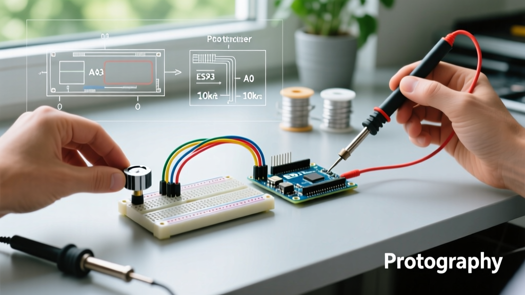
- Identify the Pins: Use a multimeter in continuity/ohms mode. Find the two pins that show the total fixed resistance (e.g., 10kΩ). These are Pin 1 and Pin 3. The remaining pin is the wiper (Pin 2).
- Connect the Rails: Wire Pin 1 to your microcontroller's logic HIGH (5V on Uno/Mega, 3.3V on Nano ESP32). Wire Pin 3 to a clean analog ground (AGND if available, otherwise standard GND).
- Connect the Signal: Wire Pin 2 (Wiper) to an ADC-capable pin (e.g., A0 on an Uno, or A1 on a Nano ESP32).
- Install the Filter: Bridge the 0.1µF capacitor between Pin 2 and Pin 3 (Ground).
Microcontroller ADC Compatibility Matrix
A common failure mode in modern maker projects occurs when migrating a legacy 5V ATmega328P sketch to a modern 3.3V ESP32-S3 based board without adjusting for ADC architecture. The ESP32's ADC is notoriously non-linear near the 0V and 3.3V rails, a quirk documented extensively in the Espressif ESP-IDF ADC Oneshot Documentation.
| Board / MCU | Logic / VREF | ADC Resolution | Input Impedance | Compatibility Quirks & Solutions |
|---|---|---|---|---|
| Arduino Uno R3 / R4 | 5.0V | 10-bit (0-1023) | ~100 MΩ | Highly linear. Standard 10kΩ pots work perfectly. R4 uses a 12-bit ADC but defaults to 10-bit in standard Arduino IDE. |
| Arduino Mega 2560 | 5.0V | 10-bit (0-1023) | ~100 MΩ | Identical to Uno, but beware of using pins A6-A15 if digital noise from adjacent PWM pins is high. |
| Nano ESP32 | 3.3V | 12-bit (0-4095) | Variable / Low | CRITICAL: Do not use full 0-3.3V range. The ADC saturates and becomes non-linear above ~2.8V. Use a voltage divider or software attenuation mapping. |
| Arduino Due (SAM3X8E) | 3.3V | 12-bit (0-4095) | High | Requires strict adherence to the 3.3V max limit. 5V signals will permanently damage the MCU. |
The Physics of Resistance Selection
Beginners often grab whatever potentiometer is in the bin, but the total resistance value drastically alters circuit behavior. Understanding the relationship between resistance, current draw, and ADC sampling is vital. As outlined in SparkFun's Voltage Divider tutorial, the potentiometer acts as a dynamic voltage divider.
Why 10kΩ is the Gold Standard
- 1kΩ Potentiometer: At 5V, this draws 5mA of continuous current. This wastes battery life in portable projects and can cause localized heating, leading to thermal drift in the resistive element.
- 10kΩ Potentiometer: Draws 0.5mA at 5V. This is the sweet spot. It provides a low enough source impedance to quickly charge the microcontroller's internal ADC sample-and-hold capacitor (typically 14pF to 50pF) without wasting excessive power.
- 100kΩ Potentiometer: Draws only 50µA, which is great for ultra-low-power sleep-mode circuits. However, the high Thevenin equivalent impedance (up to 25kΩ at the midpoint) means the ADC sampling capacitor cannot fully charge during the brief acquisition window (often just 1.5 to 12 clock cycles). This results in 'ghosting' (where reading A0 affects the subsequent reading on A1) and wildly fluctuating values.
Advanced Noise Filtering and Failure Modes
Even with the correct resistance and wiring, environmental factors can ruin your analog readings. Here is how to troubleshoot and prevent the most common edge cases encountered in industrial and advanced hobbyist setups.
1. Mechanical Wiper Bounce (Contact Noise)
Carbon track potentiometers suffer from micro-disconnections as the wiper moves over physical imperfections in the carbon. If you are using the potentiometer to control a high-speed motor via PWM or a digital-to-analog converter, this 'bounce' translates to massive voltage spikes. Solution: Implement a software moving-average filter (reading the pin 16 times and averaging) or upgrade to a conductive plastic or hybrid cermet potentiometer.
2. Ground Loop Interference
If your Arduino is powered via USB from a PC, and your potentiometer is physically mounted to a metal chassis that is also grounded, you may create a ground loop. The USB shield ground and the chassis ground will have a slight potential difference, injecting 50/60Hz AC hum into your analog readings. Solution: Isolate the potentiometer casing from the chassis using nylon shoulder washers, or implement an opto-isolator/digital isolator between the analog front-end and the MCU.
3. The 'Floating Pin' Catastrophe
When wiring multi-gang potentiometers (e.g., stereo audio pots) or using only a portion of a multi-turn trimpot, unused wiper pins left unconnected act as antennas for electromagnetic interference. Solution: Always tie unused wiper pins to their respective outer terminal or directly to ground to prevent parasitic capacitance from coupling noise into adjacent traces.
Expert Troubleshooting FAQ
Why are my analogRead() values fluctuating by ±5 even when the knob is still?
This is typically caused by USB power supply ripple or a missing bypass capacitor. The 5V rail from a standard PC USB port can have 50mV-100mV of high-frequency switching noise. Adding the 0.1µF ceramic capacitor at the wiper, combined with a 10µF electrolytic capacitor across the main VCC/GND rails of your breadboard, will stabilize the VREF and eliminate the jitter.
Can I use a 50kΩ or 100kΩ pot if I lower the ADC clock speed?
Yes. If you must use a high-impedance sensor or potentiometer to save power, you can manually adjust the ADC prescaler bits in the ATmega328P's ADCSRA register. Slowing the ADC clock from the default 125kHz down to 15kHz gives the internal sample-and-hold capacitor more time to charge through the high resistance, eliminating the 'ghosting' effect between adjacent analog pins.
How do I map the non-linear ESP32 ADC readings in Arduino IDE?
For the Arduino Nano ESP32 or generic ESP32 dev boards, do not rely on the standard map() function for precision. Instead, use the ESP-IDF's built-in ADC calibration functions (esp_adc_cal_characterize) which apply factory-stored eFuse calibration data to linearize the 12-bit output, or restrict your physical potentiometer rotation to the 10% - 80% range where the hardware ADC is naturally linear.