
The Great Misconception: PWM vs. True Analog Voltage
If you have ever used the analogWrite() function on a classic Arduino Uno R3 to dim an LED or control a motor, you were not actually generating an analog voltage. You were generating Pulse Width Modulation (PWM). The ATmega328P microcontroller lacks a native Digital-to-Analog Converter (DAC). Instead, it rapidly switches a digital pin between 0V and 5V. While human eyes and slow mechanical systems average this out, sensitive analog circuitry, audio amplifiers, and precision op-amp stages will read this as a harsh 490Hz square wave.
To achieve true analog output in Arduino projects—meaning a steady, continuous DC voltage—you must either filter the PWM signal, upgrade to a modern board with a native DAC, or interface an external I2C DAC chip. This tutorial breaks down the three most effective methods, complete with real-world component values and failure modes.
Method 1: Passive RC Low-Pass Filter (The Budget Approach)
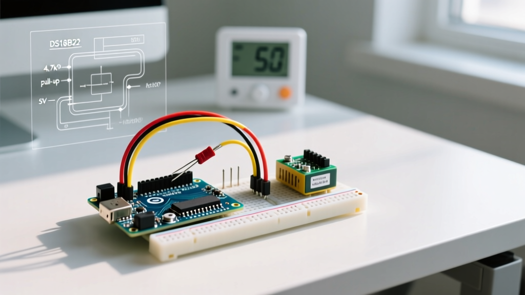
If you are locked into an ATmega-based board (like the Uno R3 or Nano) and need a smooth DC voltage under $2.00 in component costs, an RC (Resistor-Capacitor) low-pass filter is your best option. This circuit smooths the PWM square wave into a flat DC line by shunting high-frequency AC components to ground.
Calculating Your RC Components
The standard PWM frequency on Arduino Uno pins 3, 9, 10, and 11 is 490.20 Hz. (Pins 5 and 6 operate at 980.39 Hz). To filter out a 490Hz wave, your filter's cutoff frequency ($f_c$) must be significantly lower. The formula is:
f_c = 1 / (2 * π * R * C)
For a smooth output with minimal ripple, target a cutoff frequency around 10% of your PWM frequency (approx. 50Hz). Using a 10kΩ resistor and a 10µF ceramic capacitor yields a cutoff frequency of 1.59 Hz. This provides immense attenuation of the 490Hz PWM carrier, resulting in a ripple voltage of less than 5mV.
Expert Warning: The Impedance Trap
A 10kΩ series resistor means your filtered analog output has a high output impedance (10kΩ). If you connect this directly to a low-impedance load (like a 1kΩ sensor input or a motor driver), the voltage will sag drastically due to the voltage divider effect. Always buffer an RC filter output using a rail-to-rail op-amp configured as a unity-gain voltage follower. The MCP6001 or TS922 are excellent, low-cost choices for 5V Arduino systems.
Trade-off: Settling Time vs. Ripple
The time constant ($\tau = R \times C$) dictates how fast your analog voltage can change. With R=10kΩ and C=10µF, $\tau = 100$ milliseconds. It will take roughly $5\tau$ (500ms) for the output to settle within 1% of a new target voltage. If your application requires fast voltage sweeps (e.g., generating a 50Hz sine wave), an RC filter will fail. You must move to a true DAC.
Method 2: The Modern Native DAC (Arduino Uno R4 Minima/WiFi)
As of 2026, the maker ecosystem has largely embraced the Arduino Uno R4 series. Powered by the Renesas RA4M1 ARM Cortex-M4 chip, the Uno R4 features a hardware 12-bit DAC on pin A0 (labeled DAC0).
Unlocking 12-Bit Resolution
By default, the Arduino core maps analogWrite() to 8-bit (0-255) to maintain backward compatibility with legacy sketches. To access the true 12-bit resolution (0-4095) for ultra-fine voltage steps (approx. 1.22mV per step on a 5V scale), you must explicitly declare the resolution in your setup() block:
void setup() {
  analogWriteResolution(12); // Unlock 12-bit DAC resolution
}

void loop() {
  // Output exactly 2.5V (half of 5V reference)
  analogWrite(DAC0, 2048);
  delay(1000);
}
The native DAC has an output impedance of roughly 1.5kΩ, which is better than an RC filter but still requires buffering for heavy loads. Furthermore, the RA4M1 DAC can easily generate high-fidelity audio waveforms via DMA, a feat impossible with PWM filters.
Method 3: High-Precision I2C DAC (MCP4725 Breakout)
When you need true analog output on an older board, or require the DAC to remember its voltage state after a power cycle, the Microchip MCP4725 is the industry-standard I2C DAC. Breakout boards from Adafruit or SparkFun typically cost between $4.50 and $7.00.
Wiring and I2C Addressing
The MCP4725 communicates via I2C and requires only four connections: VDD (5V), GND, SDA (A4 on Uno), and SCL (A5 on Uno). The default I2C address is 0x60. If you need multiple DACs, you can pull the A0 address pin high to shift the address to 0x61.
Using the Adafruit MCP4725 Library, writing a voltage and saving it to the onboard EEPROM is trivial:
#include <Adafruit_MCP4725.h>
Adafruit_MCP4725 dac;

void setup() {
  dac.begin(0x60);
  // Write 2.5V and save to EEPROM for persistent boot state
  dac.setVoltage(2048, true);
}
Technical Comparison Matrix
| Method | Resolution | Cost (2026) | Settling Time | Drive Capability | Best Use Case |
|---|---|---|---|---|---|
| PWM + RC Filter | 8-bit (Effective) | < $0.50 | Slow (100ms+) | Very Low (Needs Op-Amp) | Static bias voltages, basic LED dimming |
| Uno R4 Native DAC | 12-bit | $20.00 (Board) | Fast (< 5µs) | Moderate (1.5kΩ Z) | Audio generation, fast control loops |
| MCP4725 I2C DAC | 12-bit | $4.50 - $7.00 | Medium (I2C Bus limited) | Low (1kΩ Z) | Persistent calibration voltages, multi-board sync |
Real-World Troubleshooting & Failure Modes
Even with the right hardware, analog output circuits frequently fail in the field due to environmental and architectural oversights. Watch out for these specific edge cases:
- Ground Loop Noise: If your Arduino is powered via USB from a noisy PC, and your analog circuit is grounded to a separate bench power supply, you will see 50/60Hz mains hum superimposed on your DAC output. Fix: Use a shared star-ground topology or an isolated DC-DC converter.
- Capacitor ESR in RC Filters: Using a cheap electrolytic capacitor instead of a multilayer ceramic capacitor (MLCC) introduces Equivalent Series Resistance (ESR). High ESR prevents the capacitor from effectively shunting the 490Hz PWM spikes, leaving a "fuzzy" oscilloscope trace. Fix: Always use X7R or C0G ceramic capacitors for PWM filtering.
- VDD as VREF: On the MCP4725, the reference voltage is tied directly to VDD. If your Arduino's 5V rail sags to 4.8V when a motor kicks on, your "precise" 2.5V analog output will instantly drop to 2.4V. Fix: Power the MCP4725 from a dedicated 5V LDO voltage regulator (like the MCP1700) separate from the Arduino's main logic rail.
References
For deeper technical specifications on microcontroller I/O and modulation techniques, consult the following authoritative resources: