
The Bottleneck in Bare-Metal AVR Prototyping
When transitioning from development boards to custom PCBs, embedded engineers and makers face a critical workflow bottleneck: programming bare-metal AVR microcontrollers. Dedicated hardware programmers like the Atmel-ICE (approximately $115) or the Pololu USB AVR Programmer v2 ($25) are reliable, but they represent an additional cost and require dedicated USB ports. For rapid prototyping, small-batch manufacturing, and educational workshops, leveraging an Arduino as ISP (In-System Programmer) remains the ultimate zero-cost workflow hack. By repurposing a standard Arduino Uno or Nano, you can flash ATtiny and ATmega chips directly via the SPI interface. However, the internet is littered with forum posts about bricked chips, failed uploads, and signature mismatches. This guide details an optimized, error-free workflow for using the Arduino as ISP in 2026, focusing on hardware stabilization, IDE configuration, and advanced command-line batch processing.
The Hardware Stack: Selecting Your Programmer and Target
Not all Arduino boards behave identically when acting as an ISP. The underlying USB-to-Serial architecture dictates how the board handles serial handshaking and reset signals.
Recommended Programmer Boards
- Arduino Uno R3 (ATmega16U2): The gold standard for ISP workflows. The ATmega16U2 USB controller provides clean serial handshaking, making the auto-reset bypass straightforward.
- Arduino Nano (Classic ATmega328P): Highly portable, but the CH340 or FT232RL USB-to-Serial chips can sometimes introduce timing quirks during the initial serial handshake. Still highly viable with proper capacitor placement.
- Avoid for ISP: The Arduino Uno R4 Minima. While an excellent board for general development, its Renesas RA4M1 ARM Cortex-M4 architecture and native USB handling require different ISP firmware and do not support the classic ArduinoISP sketch without significant modification. Stick to 8-bit AVR-based boards for the programmer role to ensure 100% compatibility with standard
avrdudeprotocols.
Target Microcontrollers
The most common targets for this workflow are the Microchip ATtiny85 (roughly $1.20 per unit in bulk) and the bare ATmega328P-PU ($2.50 - $3.00). These chips lack native USB, making SPI programming via an external ISP mandatory.
The 10µF Capacitor Rule: Preventing the Auto-Reset Trap
Critical Workflow Step: If you skip this step, your workflow will fail 90% of the time. You must disable the auto-reset feature on the programmer Arduino.
When the Arduino IDE or avrdude opens a serial connection to the programmer board, the DTR (Data Terminal Ready) line pulses low. On standard Arduino boards, this pulse is routed through a 0.1µF capacitor to the RESET pin, intentionally restarting the board so the bootloader can catch the new sketch. However, when acting as an ISP, the programmer board must stay running the ArduinoISP firmware to relay SPI data to the target chip. If the programmer resets mid-transfer, the target chip receives garbage data, resulting in a failed upload or corrupted fuse bits.
The Fix: Connect a 10µF to 22µF electrolytic capacitor between the RESET and GND pins on the programmer Arduino. The negative leg (stripe) goes to GND. This capacitor absorbs the DTR voltage spike, keeping the programmer's ATmega328P running the ISP sketch. Remember to remove this capacitor when you need to upload a new sketch to the programmer board itself.
Optimized SPI Wiring Matrix
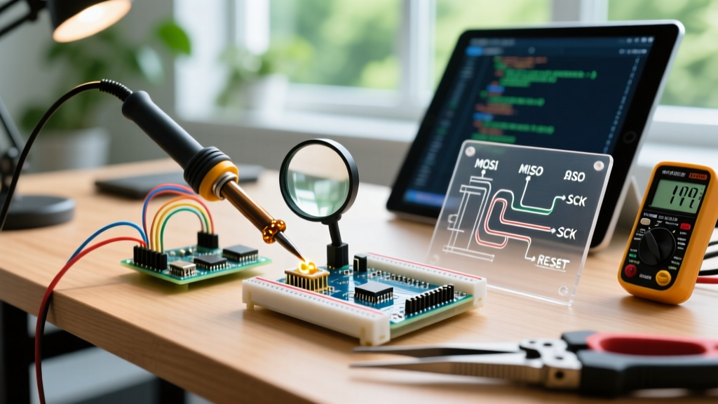
Speed and reliability in physical prototyping rely on standardized wiring. Use color-coded jumper wires to reduce cognitive load and prevent catastrophic VCC/GND reversals. Below is the definitive SPI mapping for programming an ATtiny85 or ATmega328P using an Arduino Uno as the ISP.
| Programmer (Arduino Uno) | Target (ATtiny85) | Target (ATmega328P-PU) | Wire Color Suggestion |
|---|---|---|---|
| Pin 10 (SS/RESET) | Pin 1 (PB5/RESET) | Pin 29 (PC6/RESET) | Yellow or Orange |
| Pin 11 (MOSI) | Pin 5 (PB0/MOSI) | Pin 17 (PB3/MOSI) | Green |
| Pin 12 (MISO) | Pin 6 (PB1/MISO) | Pin 18 (PB4/MISO) | Blue |
| Pin 13 (SCK) | Pin 7 (PB2/SCK) | Pin 19 (PB5/SCK) | Purple |
| 5V | Pin 8 (VCC) | Pin 7 (VCC) & Pin 20 (AVCC) | Red |
| GND | Pin 4 (GND) | Pin 8 (GND) & Pin 22 (GND) | Black |
Note: For the ATmega328P, ensure you also connect a 16MHz crystal oscillator to pins 9 and 10 with 22pF load capacitors to ground if the chip's fuse bits are currently set to require an external clock. If programming a fresh from-factory chip, it defaults to the 1MHz internal oscillator and does not require a crystal for the initial flash.
Step-by-Step: Flashing the ArduinoISP Firmware
Before programming your target, the programmer board must be loaded with the correct firmware. According to the official ArduinoISP documentation, the setup is straightforward, but modern IDE versions require specific menu selections.
- Remove the 10µF capacitor from the programmer board's RESET and GND pins.
- Open Arduino IDE 2.3.x (or newer). Navigate to File > Examples > 11.ArduinoISP > ArduinoISP.
- Set your Board to Arduino Uno (or Nano) and select the correct COM port.
- Upload the sketch. Verify the onboard LED on Pin 9 pulses slowly (the heartbeat indicator).
- Reinstall the 10µF capacitor across RESET and GND.
- Wire the target chip according to the matrix above.
- In the IDE, go to Tools > Programmer and select Arduino as ISP. (Do not select 'ArduinoISP'—the naming convention in the IDE can be confusing; the correct option is explicitly 'Arduino as ISP').
- Select your target board (e.g., ATtiny25/45/85 via the ATTinyCore board manager package) and click Upload Using Programmer.
Advanced Workflow: Bypassing the IDE with AVRDUDE
For makers producing small batches (10-50 units) or integrating programming into automated test jigs, the Arduino IDE is too slow. The IDE recompiles the sketch every time, even if the binary hasn't changed. The optimized workflow relies on calling AVRDUDE directly from the command line or a shell script.
First, compile your sketch in the IDE and select Sketch > Export Compiled Binary. This generates a .hex file in your sketch folder. Next, use a bash or batch script to flash the target chip in milliseconds.
Windows Batch Script Example (flash_target.bat):
@echo off
set COM_PORT=COM3
set HEX_FILE=firmware_v2.hex
avrdude -c arduino -p attiny85 -P %COM_PORT% -b 19200 -U flash:w:%HEX_FILE%:i -U lfuse:w:0xE2:m -U hfuse:w:0xDF:m -U efuse:w:0xFF:m
echo Programming Complete.
Command Breakdown for Workflow Optimization:
-c arduino: Tells AVRDUDE to use the Arduino ISP protocol.-b 19200: The default baud rate for the ArduinoISP sketch. Changing this in the sketch and CLI can speed up transfers, but 19200 is the most stable baseline.-U flash:w:%HEX_FILE%:i: Writes the pre-compiled hex file directly to flash memory without recompilation.-U lfuse:w:0xE2:m: Explicitly sets the low fuse to 0xE2, configuring the ATtiny85 to use the internal 8MHz oscillator with the divide-by-8 fuse disabled. Explicitly defining fuses in your batch script prevents 'bricked' chips caused by accidental IDE fuse misconfigurations.
Troubleshooting Matrix: Signatures and Fuse Bricking
Even with an optimized workflow, bare-metal programming introduces edge cases. Below is a diagnostic matrix for the most common avrdude errors encountered when using the Arduino as ISP.
| Error Message | Root Cause | Optimized Solution |
|---|---|---|
stk500_recv(): programmer is not responding | The programmer Arduino is resetting upon serial connection, or the COM port is locked. | Verify the 10µF capacitor is installed between RESET and GND on the programmer. Close any serial monitors or 3D printer host software (like OctoPrint or Cura) that might be polling the COM port. |
Yikes! Invalid device signature (0x000000) | No communication with target chip. VCC/GND missing, or target chip is completely dead. | Check power rails with a multimeter. Ensure the target chip is seated correctly in the breadboard. Verify the 10µF capacitor hasn't shorted the programmer's RESET pin permanently to GND. |
Invalid device signature (0xffffff) | MOSI/MISO/SCK lines are crossed, or target chip is in a high-voltage reset state. | Swap MOSI and MISO wires. Ensure the target RESET pin is being pulled high (10kΩ resistor to VCC) when not actively being pulled low by the programmer's Pin 10. |
Expected signature for ATtiny85 is 1E 93 0B (Mismatch) | Target chip requires an external crystal (fuse bits previously set), but none is connected. | Connect a temporary 16MHz crystal and 22pF capacitors to the target's XTAL pins. Re-flash the chip with a sketch that resets the fuse bits to the internal 8MHz oscillator, then remove the crystal. |
A Note on 'Bricked' Chips and High-Voltage Rescue
If you accidentally disable the RESET pin on an ATtiny85 (by setting the RSTDISBL fuse), the chip will no longer respond to standard SPI programming via the Arduino as ISP. The SPI interface shares the RESET pin, and disabling it severs the programming pathway. Do not throw the chip away. You can rescue it using a High-Voltage Serial Programmer (HVSP). You can build a dedicated HVSP rescue jig using a 12V DC boost converter and a secondary ATmega328P to apply 12V to the target's RESET pin, temporarily re-enabling SPI and allowing you to correct the fuse bits.
Conclusion
Using the Arduino as ISP is more than just a cost-saving measure; when integrated into a disciplined workflow, it becomes a highly efficient tool for embedded development. By standardizing your wiring matrix, enforcing the 10µF capacitor rule, and transitioning to command-line AVRDUDE batch scripting, you eliminate the friction of bare-metal programming. This ensures your focus remains on firmware logic and hardware design, rather than debugging serial handshakes and corrupted fuse bits.