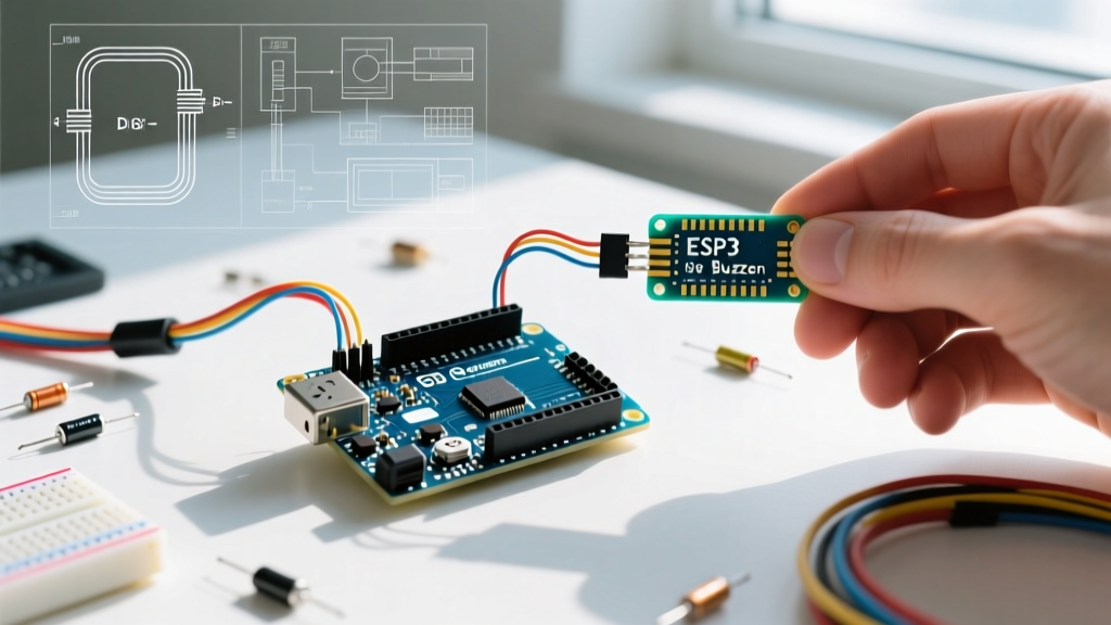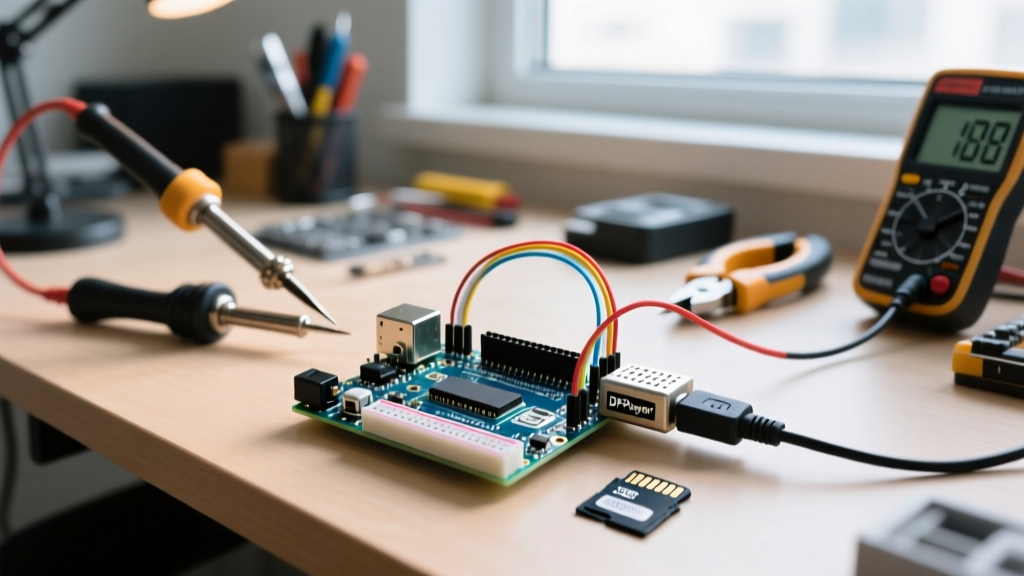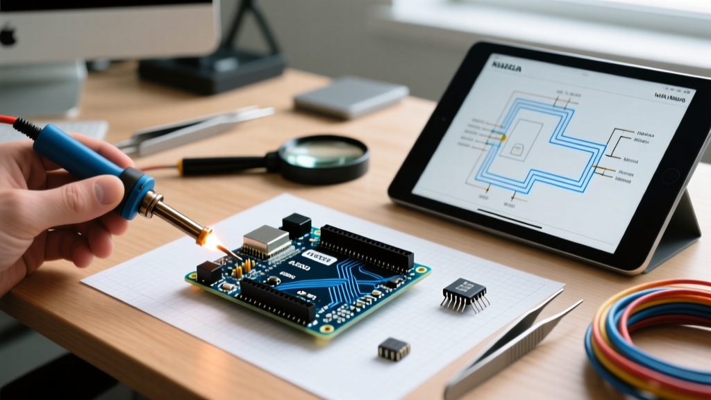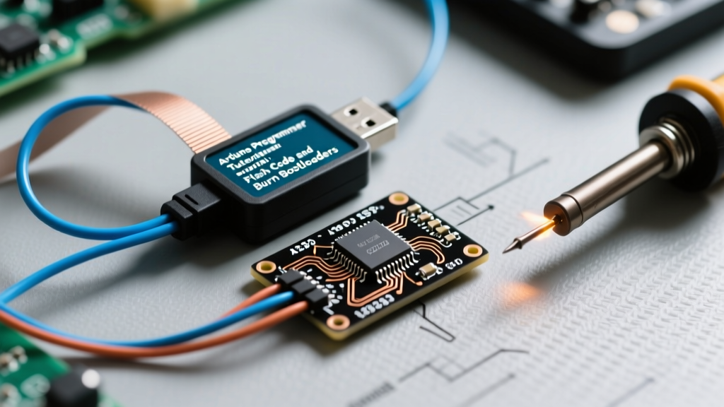

Why Use a Dedicated Arduino Programmer?
When developing custom PCBs or working with bare ATmega328P-PU microcontrollers, relying on the default serial bootloader is often inefficient. The bootloader consumes 2KB of precious flash memory, introduces a 1-to-2-second delay on every power cycle, and requires a dedicated USB-to-Serial (UART) chip like the CH340 or FT232RL. By utilizing a dedicated hardware Arduino programmer via the ICSP (In-Circuit Serial Programming) header, you bypass the UART entirely, write directly to the flash memory, and can even recover 'bricked' chips that have corrupted bootloaders or misconfigured fuse bits.
2026 Hardware Programmer Comparison Matrix
As of 2026, the market has shifted toward USB-C connectivity, though legacy Mini-USB models remain prevalent. Below is a comparison of the most reliable programmers for AVR-based Arduino boards.
| Programmer Model | Avg. Price (2026) | Connector | Best Use Case | Driver Support |
|---|---|---|---|---|
| USBasp (Clone) | $4.00 - $7.00 | USB-A / USB-C | Hobbyists, bulk flashing, budget builds | Requires Zadig/libusb-win32 |
| Pololu USB AVR Programmer v2.1 | $18.95 | USB-C | Professional prototyping, reliable CI/CD | Native Windows 11/12 & Linux |
| Arduino as ISP (DIY) | $25.00 (Cost of donor Uno) | USB-B / USB-C | Emergency recovery, field repairs | Native (Uses standard Arduino core) |
| AVRISP mkII (Clone) | $12.00 - $15.00 | Mini-USB | Legacy Atmel Studio integration | Jungo / libusb |
Prerequisites: The Barebones ATmega328P Circuit
Before connecting your Arduino programmer, you must ensure the target microcontroller is wired correctly on a breadboard or custom PCB. A bare ATmega328P-PU will not function without a clock source and proper decoupling.
- Target IC: ATmega328P-PU (DIP-28 package)
- Clock Source: 16MHz HC49S Crystal Oscillator
- Load Capacitors: 2x 22pF ceramic capacitors (from each crystal leg to GND)
- Decoupling: 100nF (0.1µF) capacitor between VCC (Pin 7) and GND (Pin 8), and AVCC (Pin 20) and GND (Pin 22)
- Pull-up Resistor: 10kΩ between RESET (Pin 1) and VCC
- ICSP Header: 2x3 male pin header (2.54mm pitch)
Standard 6-Pin ICSP Pinout
When looking at the male ICSP header on your board with the notch facing up, the pinout is as follows. Always verify with your specific board's silkscreen, as some manufacturers mirror the layout.
- MISO (Master In Slave Out)
- VCC (Target Power - usually 5V or 3.3V depending on board)
- SCK (Serial Clock)
- MOSI (Master Out Slave In)
- RESET (Active Low)
- GND (Ground)
Step-by-Step: Burning the Bootloader
Burning the bootloader sets the microcontroller's fuse bits to expect an external 16MHz clock and reserves the upper 2KB of flash for the Optiboot serial bootloader.
Step 1: Physical Connection
Connect your chosen programmer (e.g., USBasp) to the 6-pin ICSP header. Ensure the ribbon cable's red stripe (Pin 1 indicator) aligns with the MISO pin on the target board. Crucial Note: If your target board is completely unpowered and lacks its own voltage regulator, ensure your programmer has a 5V jumper set and is capable of sourcing at least 50mA to power the target IC during programming.
Step 2: IDE Configuration
Open the Arduino IDE (version 2.3.x or newer). Navigate to Tools > Board and select Arduino Uno (assuming you are targeting a standard 16MHz ATmega328P). Next, go to Tools > Port and select the COM port assigned to your programmer. If using a USBasp on Windows, you must use the AVRDUDE backend via Zadig to install the libusbK driver, otherwise the IDE will throw a 'Programmer not found' error.
Step 3: Execute the Burn
Navigate to Tools > Programmer and select your specific hardware (e.g., 'USBasp'). Finally, click Tools > Burn Bootloader. The IDE will invoke AVRDUDE in the background. You should see a success message indicating the fuse bits have been written and the Optiboot HEX file has been flashed. This process typically takes 4 to 8 seconds.
Uploading Sketches Directly via ICSP
Once the bootloader is burned, you can continue using the serial UART. However, if you are deploying a production node and want to reclaim the 2KB bootloader space and eliminate the boot delay, you can upload sketches directly via the programmer.
Instead of clicking the standard 'Upload' button, go to Sketch > Upload Using Programmer (or press Ctrl + Shift + U). This command writes your compiled .hex file starting at memory address 0x0000, effectively overwriting and erasing the bootloader. To use the serial monitor or upload via UART again in the future, you will need to repeat the 'Burn Bootloader' process.
Advanced Troubleshooting & Failure Modes
When working with raw ICSP programming, AVRDUDE errors are common. Here is how to diagnose the most frequent roadblocks encountered in the field.
Error:
avrdude: error: program enable: target doesn't answer. (rc = -1)Diagnosis: The programmer cannot establish an SPI clock with the target. This usually means the target IC is unpowered, the RESET line is being held low by an external circuit (like a 100nF auto-reset capacitor on custom PCBs), or the wiring is incorrect.
Fix: Disconnect any auto-reset capacitors. Verify VCC at Pin 7 with a multimeter. Ensure the 10kΩ pull-up resistor is present on the RESET line.
Error:
avrdude: Expected signature for ATmega328P is 1E 95 0F. Double check chip, or use -F to override this check.Diagnosis: The programmer is reading a device signature that doesn't match the ATmega328P. If you are using a brand new chip from a reputable supplier, this almost always indicates a clock failure. The factory default fuse settings expect an internal 8MHz RC oscillator, but if the chip was previously configured for an external crystal and the crystal is missing or broken, the chip cannot generate a clock signal to run the SPI interface.
Fix: Temporarily connect a 5V square wave signal (from a function generator or another Arduino pin toggling at 1MHz) directly to the XTAL1 pin (Pin 9) to provide an artificial clock, then burn the bootloader to reset the fuses.
Understanding Fuse Bits for Custom Clock Configurations
According to the ArduinoISP Official Documentation, the bootloader burn process automatically calculates the fuse bytes based on your boards.txt selection. However, for low-power battery-operated nodes, you may want to run the ATmega328P on its internal 8MHz oscillator, eliminating the external crystal and 22pF capacitors to save BOM costs and board space.
To achieve this, you must edit your IDE's boards.txt file or use a custom hardware package like 'MiniCore'. The specific fuse bytes for an 8MHz internal clock with Brown-Out Detection (BOD) set to 2.7V are:
- Low Fuse:
0xE2(CKSEL = 0010 for 8MHz internal) - High Fuse:
0xDE(BOOTRST enabled, 2KB bootloader section) - Extended Fuse:
0xFD(BODLEVEL = 2.7V)
Mastering these fuse configurations and utilizing a dedicated Arduino programmer transforms you from a simple sketch-uploader into a capable embedded systems engineer, ready to design and deploy standalone, production-grade AVR hardware.