
The Arduino 2560 in 2026: Beyond the Blink Sketch
Despite the proliferation of 32-bit ARM Cortex-M boards and ESP32 microcontrollers, the Arduino Mega 2560 remains an undisputed workhorse for large-scale DIY engineering. From Marlin-based 3D printer control boards to GRBL CNC routers and massive DMX lighting arrays, its 54 digital I/O pins and 16 analog inputs provide unmatched physical connectivity. However, treating the Mega 2560 like a standard Uno is a critical workflow mistake. Its sheer scale introduces unique bottlenecks in memory management, power distribution, and upload latency. This guide details advanced workflow optimizations to maximize the efficiency, reliability, and compilation speed of your Arduino 2560 projects.
Hardware Selection: Genuine Rev3 vs. High-Quality Clones
Your workflow begins with hardware procurement. In 2026, a genuine Arduino Mega 2560 Rev3 retails for approximately $48 to $52. Premium clones from manufacturers like Elegoo or DFRobot cost between $16 and $22. The primary architectural difference lies in the USB-to-Serial interface.
- Genuine Boards: Utilize the ATmega16U2 chip. This allows for native HID (Human Interface Device) emulation via LUFA firmware, meaning your Mega can act as a native keyboard or MIDI controller without custom drivers.
- Clone Boards: Typically use the CH340G or CH340C USB-to-Serial chip. While modern Windows 11 and macOS environments include native CH340 drivers, these chips cannot handle native HID emulation and occasionally struggle with high-baud-rate serial buffering during massive data logging.
Workflow Tip: If your project requires heavy serial debugging at 2000000 baud (supported by the ATmega2560 hardware UART), stick to the genuine ATmega16U2 boards or high-end clones that explicitly advertise an upgraded serial buffer.
Power Distribution: Bypassing the LDO Thermal Throttle
A frequent point of failure in large Mega 2560 projects is the onboard voltage regulator. The Rev3 board uses an NCP1117ST50T3G 5V LDO (Low Dropout) regulator. While rated for 1A, the SOT-223 package lacks adequate heatsinking on the PCB.
The Thermal Math: If you power the Mega via the barrel jack at 12V and draw 600mA for a servo array, the LDO must dissipate 4.2 Watts of heat [(12V - 5V) × 0.6A]. This will trigger the LDO's internal thermal shutdown within minutes, causing random MCU resets.
Optimized Power Workflow: For any project drawing more than 300mA total on the 5V rail, abandon the barrel jack. Use a dedicated, external buck converter (like the LM2596 or a modern synchronous MP2315 module) to step down your main power supply to exactly 5.1V, and inject it directly into the 5V and GND header pins. Warning: Never connect USB power simultaneously when injecting 5V directly, or you will backfeed and destroy your computer's USB port.
Memory Management: Conquering the 8KB SRAM Limit
The ATmega2560 boasts 256KB of Flash memory, but its SRAM is strictly limited to 8KB. When building complex state machines or utilizing large lookup tables, SRAM exhaustion leads to heap/stack collisions and silent, catastrophic reboots. Below is the memory architecture breakdown and optimization strategy:
| Memory Type | Capacity | Primary Use Case | Optimization Technique |
|---|---|---|---|
| Flash | 256 KB | Sketch storage, constants | Use PROGMEM for large arrays |
| SRAM | 8 KB | Variables, heap, stack | Use F() macro for serial strings |
| EEPROM | 4 KB | Persistent settings, calibration | Implement wear-leveling algorithms |
The F() Macro and PROGMEM
By default, the Arduino compiler copies all string literals into SRAM at runtime. A single verbose debug statement like Serial.println("Initializing sensor array on I2C bus..."); consumes 42 bytes of precious SRAM. Multiply this across a 15,000-line sketch, and you will easily exhaust the 8KB limit.
Always wrap static strings in the F() macro: Serial.println(F("Initializing sensor array..."));. This forces the compiler to leave the string in Flash memory and fetch it byte-by-byte during execution. For massive datasets, such as sine-wave lookup tables for DAC generation or large ASCII art arrays, utilize the avr-libc PROGMEM library to explicitly bind arrays to Flash.
The "!!!" Bootloader Edge Case
One of the most notorious, yet poorly documented, edge cases specific to the Arduino 2560 is the STK500 v2 bootloader bug. The original factory bootloader contains a debug monitor mode that is accidentally triggered if it encounters three consecutive exclamation marks (!!!) in the flash memory during the upload verification phase.
Symptoms: Your sketch compiles perfectly, but the upload hangs at 95%, eventually failing with an avrdude: stk500v2_ReceivedMessage(): timeout error.
Workflow Fix: Never use !!! in your string literals or comments that might be parsed into the binary. If you inherit a legacy codebase that triggers this bug, the permanent solution is to connect an external ICSP programmer and flash the modern, Optiboot-based Mega bootloader, which entirely removes this vulnerability while freeing up 6KB of Flash space.
Bypassing the Serial Bottleneck: ICSP Flashing
Uploading a 180KB sketch via the standard USB serial connection at 115200 baud takes roughly 25 to 30 seconds. In a rapid-iteration workflow, this latency destroys momentum. Furthermore, the default bootloader consumes the first 8KB of Flash memory.
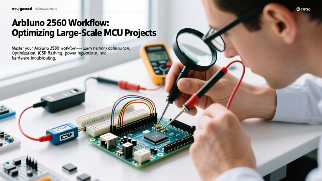
The ICSP Workflow: Invest in a dedicated ISP programmer, such as the $14 Pololu USB AVR Programmer v2.1 or a generic $5 USBasp. By connecting to the 2x3 ICSP header near the ATmega2560 chip, you bypass the bootloader entirely.
- Speed: Upload times drop from 30 seconds to under 4 seconds.
- Capacity: You reclaim the 8KB bootloader partition, giving you the full 256KB for your application.
- Reliability: ICSP flashing completely eliminates serial timeout errors caused by noisy USB cables or ground loops.
To implement this in the Arduino IDE, simply select Tools > Programmer > USBasp (or your specific model), and use Sketch > Upload Using Programmer.
Pin Mapping and I2C Traps
Migrating a prototype from an Uno to a Mega 2560 often breaks I2C communication. On the Uno, the I2C lines (SDA/SCL) are hardcoded to analog pins A4 and A5. On the Mega 2560, the hardware I2C lines are mapped to Digital Pin 20 (SDA) and Digital Pin 21 (SCL).
If you are using legacy Uno shields, I2C devices will fail to initialize. The optimized workflow is to abandon A4/A5 for I2C entirely and use the dedicated 4-pin I2C header located next to the USB port. This header duplicates pins 20 and 21 and includes dedicated 3.3V, 5V, and GND rails.
Signal Integrity Note: The Mega 2560 does not always populate internal pull-up resistors on the I2C lines depending on the board revision and manufacturer. If you are running I2C traces longer than 15cm to external sensors, you must add external 4.7kΩ pull-up resistors to both SDA and SCL lines to prevent bus capacitance from corrupting the data packets.
Conclusion
Optimizing your Arduino 2560 workflow requires shifting from a "plug-and-play" mindset to an embedded systems engineering approach. By managing power thermals, strictly enforcing SRAM discipline via PROGMEM, adopting ICSP flashing for rapid iteration, and respecting the hardware I2C pinouts, you transform the Mega 2560 from a bulky beginner board into a highly reliable, industrial-grade prototyping platform. For deeper insights into AVR memory constraints, refer to the official Arduino Memory Guide.