
The Hidden Cost of Inefficient Logic in Microcontrollers
When developing for modern microcontrollers like the ESP32-S3 or the Raspberry Pi Pico 2 (RP2350), it is remarkably easy to take memory and processing overhead for granted. However, true workflow optimization in embedded systems demands a rigorous understanding of fundamental data types. This is especially critical when your code must remain backward-compatible with legacy 8-bit architectures like the ATmega328P (found in the Arduino Uno R3) or the ATtiny85, where SRAM is measured in mere kilobytes or even bytes.
The boolean in Arduino is the absolute backbone of state management, sensor debouncing, and logic gating. Yet, it is frequently misused by both hobbyists and intermediate developers. Sloppy boolean management leads to SRAM bloat, blocking execution loops, and devastating race conditions in Interrupt Service Routines (ISRs). By rethinking how you declare, store, and evaluate boolean states, you can drastically reduce your memory footprint, eliminate blocking delays, and create highly responsive, professional-grade firmware.
Under the Hood: Memory Allocation for Booleans
In the Arduino ecosystem, developers often use the boolean keyword interchangeably with the standard C++ bool. Since Arduino IDE 1.0, boolean is simply a typedef for the native C++ bool. A pervasive misconception among beginners is that a boolean consumes only a single bit of memory because it only holds two states: true (1) or false (0).
In reality, the Arduino compiler allocates a full byte (8 bits) for every standard boolean variable. This design choice maintains memory alignment boundaries and ensures the CPU can fetch the variable in a single clock cycle. However, if your workflow involves tracking 50 different system flags, you are silently consuming 50 bytes of precious SRAM—a massive penalty on an ATtiny85 with only 512 bytes of total SRAM.
| Data Type | Memory Size | Value Range | Optimal Workflow Use |
|---|---|---|---|
| boolean / bool | 1 Byte (8 bits) | true / false | Standard state flags, simple logic gates, local loop variables |
| uint8_t | 1 Byte (8 bits) | 0 to 255 | Counters, PWM values, sensor thresholds, state machine enums |
| Bitfield (struct) | 1 Bit (packed) | 0 or 1 | Massive state machines, extreme SRAM saving, global system flags |
Workflow Strategy 1: Non-Blocking State Machines
A primary workflow optimization involves replacing nested if/else statements and delay() functions with boolean-driven state machines. Using a boolean flag to track whether a process is 'active' allows your loop() function to execute thousands of times per second, keeping the microcontroller responsive to external inputs.
Consider a scenario where a motor must run for 3 seconds after a button press. The amateur workflow uses delay(3000), effectively paralyzing the MCU. The optimized workflow uses a boolean flag paired with the millis() timer:
Optimization Rule of Thumb: Never use a boolean to trigger a blocking delay. Instead, use the boolean to toggle a state machine that continuously evaluates millis() - previousMillis >= interval. This single workflow shift resolves 90% of 'unresponsive Arduino' complaints on maker forums.
The Volatile Keyword: Preventing Compiler Optimization Bugs
When a boolean variable is updated inside an Interrupt Service Routine (ISR) but evaluated inside the main loop(), it must be declared with the volatile keyword. For example: volatile boolean motionDetected = false;.
Without volatile, the GCC compiler's optimizer assumes that the main loop is the only place the variable can change. It will cache the boolean's initial false state in a CPU register and never re-read it from SRAM, causing your code to permanently ignore the interrupt. According to the AVR Libc documentation on volatile variables, this keyword forces the compiler to fetch the value from SRAM on every single evaluation, ensuring ISR updates are recognized immediately. This is a critical edge case that causes endless debugging headaches for developers migrating from standard desktop C++ to embedded systems.
Workflow Strategy 2: Extreme SRAM Optimization via Bitfields
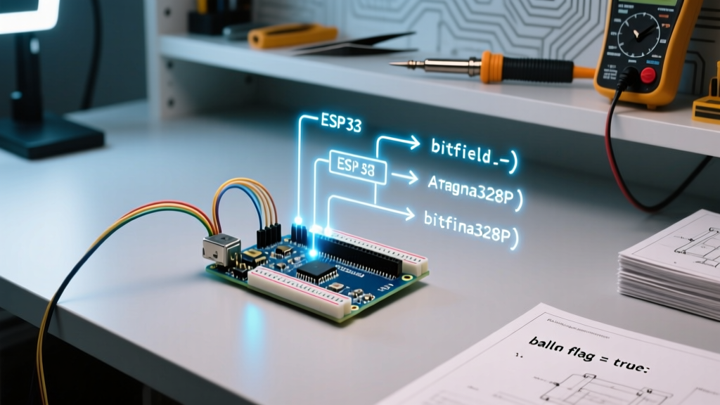
When working with memory-constrained boards like the ATmega328P (2KB SRAM) or designing complex appliances with dozens of status flags, standard booleans become a liability. The professional workflow leverages C++ bitfields to pack up to eight boolean states into a single byte.
By defining a struct with specific bit-width allocations, you instruct the compiler to handle the bitwise masking and shifting automatically. This provides the readability of standard booleans with the memory efficiency of raw bitwise operations.
Implementing a Bitfield State Tracker
- Define the Structure: Create a global struct where each variable is assigned a width of
: 1.struct SystemFlags { bool motorActive : 1; bool ledError : 1; bool wifiConnected : 1; bool sensorCalibrated : 1; bool emergencyStop : 1; } flags; - Initialize States: In your
setup(), initialize the struct to zero usingmemset(&flags, 0, sizeof(flags));to ensure a clean slate. - Evaluate in Loop: Read and write exactly as you would a normal boolean:
if (flags.wifiConnected && !flags.emergencyStop) { ... }.
While this technique saves 7 bytes of SRAM for every 8 flags, it is important to note the trade-off. As detailed in C++ bitfield specifications, accessing a bitfield requires a read-modify-write operation at the CPU level. On an 8-bit AVR chip, this costs a few extra clock cycles compared to reading a full byte. Therefore, reserve bitfields for global state tracking rather than high-frequency variables evaluated inside fast PWM or timer interrupts.
Hardware Edge Cases: Floating Pins and Erratic Booleans
A perfectly optimized boolean workflow will still fail if the underlying hardware input is unstable. A common failure mode occurs when a physical button or limit switch is wired to a digital pin without a pull-down resistor. The pin becomes 'floating,' acting as an antenna that picks up electromagnetic interference. This causes the boolean variable reading the pin to flip between true and false hundreds of times per second.
The Fix: Eliminate external resistors and messy breadboard wiring by enabling the microcontroller's internal pull-up resistors. Configure your pin using pinMode(buttonPin, INPUT_PULLUP);. This engages an internal 20k-50k ohm resistor, holding the pin firmly at HIGH (true) until the button bridges it to ground. Remember to invert your logic in code: a pressed button will now read as LOW (false). For a deeper understanding of how the compiler interprets these digital reads, consult the official Arduino boolean reference.
Advanced Debouncing Without External Libraries
Relying on heavy third-party debouncing libraries consumes unnecessary flash memory and introduces opaque background timers. An optimized workflow handles mechanical switch bounce using a simple boolean latch combined with a timestamp.
- Step 1: Declare
boolean lastButtonState = HIGH;andboolean currentButtonState = HIGH;. - Step 2: Read the pin. If the current reading differs from
lastButtonState, reset yourmillis()timer. - Step 3: If the state has remained consistent for more than 50 milliseconds (the standard bounce window for most tactile Omron switches), update your primary
boolean buttonTriggeredflag.
This manual approach guarantees deterministic timing, uses less than 10 bytes of SRAM, and keeps your codebase entirely transparent and dependency-free.
Summary Checklist for Boolean Optimization
Before compiling and flashing your next firmware update, run your code through this optimization checklist:
- Audit Global Flags: Are you using more than 8 global booleans? If so, refactor them into a packed bitfield struct to reclaim SRAM.
- Verify ISR Variables: Does every boolean modified inside an
ISR()carry thevolatilekeyword? - Eliminate Blocking Logic: Are any boolean state changes immediately followed by a
delay()? Refactor into amillis()-based state machine. - Secure Hardware Inputs: Are all physical inputs utilizing
INPUT_PULLUPto prevent floating pins from corrupting your boolean logic?
By treating the boolean not just as a simple true/false switch, but as a fundamental unit of system architecture, you elevate your embedded workflows from fragile prototypes to robust, production-ready engineering.